
Automatic sheet foot pad laminating machine

A laminating machine and material foot technology, which is applied to conveyor objects, lamination auxiliary operations, lamination, etc., can solve problems such as low production efficiency, shortening sheet material transfer time, and low lamination efficiency.

Pending Publication Date: 2019-01-04
林勇
View PDF2 Cites 5 Cited by
  • Summary
  • Abstract
  • Description
  • Claims
  • Application Information

AI Technical Summary

Problems solved by technology

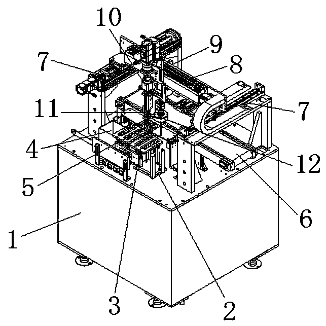
[0003] The technical problem to be solved by the present invention is to provide an automatic laminating machine for sheet material foot pads, which can complete the ejection, suction, plane shifting, clamping, and CCD shooting of the sheet materials on the top surface of the cabinet. , Three-dimensional space movement to adjust the grabbing position, precise grasping of foot pads, three-dimensional space mobile feeding, three-dimensional space mobile positioning, three-dimensional space spinning and laminating and blanking and other operations, the lamination accuracy is high, the lamination effect is good and The yield rate of the product is high, and the overall footprint and space of the equipment are small, so that it can effectively shorten the transmission time of the sheet material, so that the production efficiency and production capacity can be significantly improved. It not only solves the traditional problem of attaching the sheet material The combination of manual positioning and manual lamination has the problems of inaccurate lamination positioning, low lamination efficiency, poor lamination effect, high labor intensity of workers and high labor cost of enterprises. It also solves the problems of current automatic lamination equipment The use of flow-type conveying and feeding has the problems of large equipment volume, long feeding and conveying time, low production efficiency and high equipment manufacturing cost.

Method used


Image

  • Automatic sheet foot pad laminating machine
  • Automatic sheet foot pad laminating machine
  • Automatic sheet foot pad laminating machine

Examples


Embodiment Construction

[0026]In order to facilitate the understanding of the present invention, the present invention will be described more fully below with reference to the associated drawings. Preferred embodiments of the invention are shown in the accompanying drawings. However, the present invention can be embodied in many different forms and is not limited to the embodiments described herein. On the contrary, the purpose of providing these embodiments is to make the disclosure of the present invention more thorough and comprehensive.

[0027] Unless otherwise defined, all technical and scientific terms used herein have the same meaning as commonly understood by one of ordinary skill in the technical field of the invention.

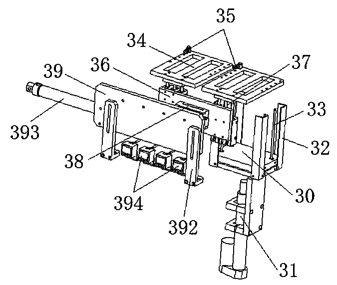
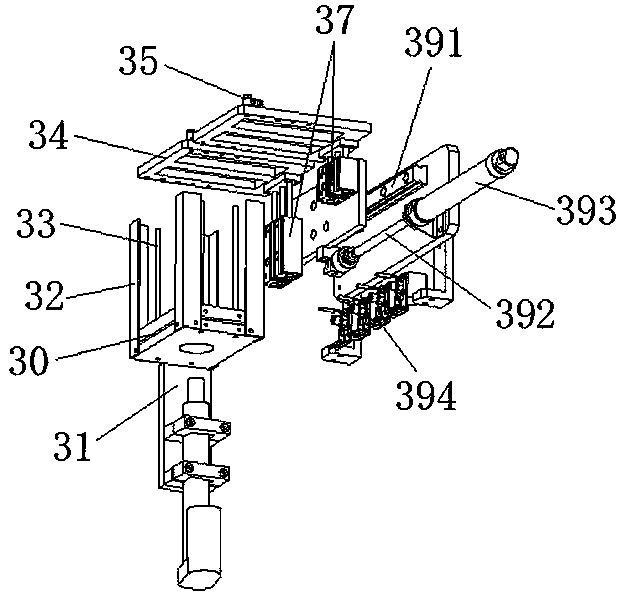
[0028] In this example, refer to Figure 1 to Figure 6 As shown, a kind of sheet material foot pad automatic laminating machine of the present invention comprises cabinet 1, and the top surface of cabinet 1 is provided with stacking platform 2, and the upper surface of s...


PUM


Abstract

The invention discloses an automatic sheet foot pad laminating machine, which comprises a feeding mechanism, a conveying mechanism, longitudinal transmission modules, a bilateral transmission module,a vertical transmission module, a laminating rotary module, a clamping mechanism, a CCD visual positioning system and the like. A series of operations including jacking, sucking, planar transferring,clamping, CCD shooting, three-dimensional spatial foot pad grabbing position regulation, accurate foot pad grabbing, three-dimensional spatial movable conveying, three-dimensional spatial movable positioning, three-dimensional spatial spinning lamination, discharging and the like are completed on the top surface of a case. The problem of large floor area of traditional assembly line operating equipment is solved while sheet conveying time can be shortened, so that production efficiency and productivity are improved; the production process is free of artificial operations, so that labor cost ofenterprises is reduced; by joint use with the CCD visual positioning system and the transmission modules in different moving directions, high laminating precision, excellent laminating effects and the like are achieved.

Description

technical field [0001] The invention relates to an automatic bonding machine for sheet material pads. Background technique [0002] Traditional lamination of sheet materials is generally operated by manual positioning and manual lamination. This operation method has the disadvantages of inaccurate lamination positioning, low lamination efficiency, poor lamination effect, high labor intensity of workers and labor of enterprises. High cost and other shortcomings, it does not meet the requirements of large-scale mass production and intelligent production of enterprises. Later, some automatic laminating equipment appeared on the market, but because it uses flowing water for feeding, the volume of the equipment is relatively large, and its structural design is not scientific and reasonable, and the time required for assembly line production is long. Efficiency still needs to be further improved and production cost still needs to be further reduced. Contents of the invention ...

Claims


Application Information

Patent Timeline
Patent Type & Authority Applications(China)
IPC IPC(8): B32B38/10B65G47/91
CPCB65G47/912B65G47/917B32B38/10
Inventor 林勇谭清立
Owner 林勇
Learn More