
Method of reinforcing surface structure by laser shock

A technology of laser shock strengthening and surface structure, which is used in heat treatment equipment, heat treatment process control, manufacturing tools, etc. It can solve the problems of inaccurate intensity control of laser shock treatment, and achieve the effect of improving uniformity and ensuring consistency.

Active Publication Date: 2019-01-04
GUANGDONG UNIV OF TECH
View PDF1 Cites 2 Cited by
  • Summary
  • Abstract
  • Description
  • Claims
  • Application Information

AI Technical Summary

Problems solved by technology

However, this method uses the same laser energy distribution for the same small area, ignoring the curvature change of each small area, and the intensity control of laser shock treatment is not accurate enough.

Method used


Image

  • Method of reinforcing surface structure by laser shock
  • Method of reinforcing surface structure by laser shock
  • Method of reinforcing surface structure by laser shock

Examples


Embodiment 1

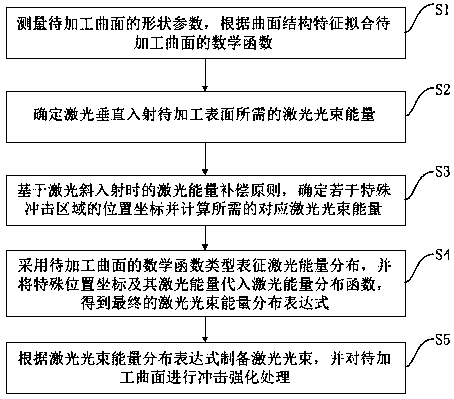
[0035] Such as figure 1 Shown is the flowchart of the method for laser shock strengthening curved surface structure of the present invention, comprises the following steps:

[0036] S1. Measuring the shape parameters of the surface to be processed, deriving the mathematical function type of the structural features of the surface, and fitting the mathematical function expression of the surface to be processed;

[0037] S2. According to the surface strengthening requirements of the material, determine the laser beam energy E required for the laser to be vertically incident on the surface to be processed 0 ;

[0038] S3. Based on the principle of laser energy compensation under the condition of laser oblique incidence, determine the position coordinates of several special impact areas and calculate the corresponding required laser beam energy E;

[0039] S4. Use the mathematical function type of the surface to be processed to characterize the laser energy distribution to obtain...

Embodiment 2

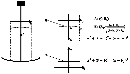
[0054] This embodiment is the application of the equation that the mathematical function type of the plane or curved surface to be processed in Embodiment 1 is a circle. In this embodiment:

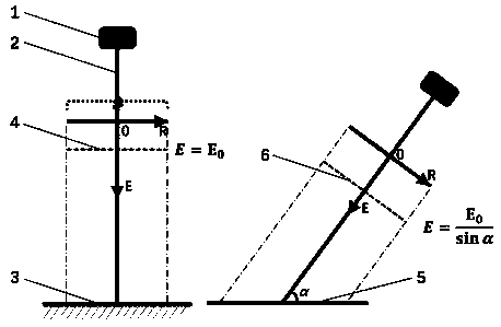
[0055] Such as figure 2 As shown, when the laser beam 2 is vertically incident on the plane 3 to be processed, the energy of the laser beam is E 0 , its distribution is represented by plane 4; when the laser beam 2 obliquely hits the plane 5 to be processed, the angle between the laser beam 2 obliquely incident on the plane to be processed and the horizontal plane of the laser 1 is α, then the angle between the laser beam 2 obliquely incident on the plane to be processed Laser beam energy E needs to be increased to Its distribution is represented by plane 6 .

[0056] Such as Figure 4 As shown, when the laser beam 2 is vertically incident on the curved surface 9 to be processed, the energy distribution of the laser beam 2 is represented by a curved surface 10; In this embodiment, t...


PUM


Abstract

The invention relates to the technical field of material surface reinforcement, in particular to a method of reinforcing a surface structure by laser shock. The method comprises: measuring shape parameters of a surface to be processed, and fitting a math function of the surface to be processed, according to structural characteristics of the surface; determining laser beam energy required by laserto perpendicularly enter the surface to be processed; determining positional coordinates of a plurality of special shock areas, and calculating required corresponding laser beam energy; acquiring a final laser beam energy distribution expression; preparing a laser beam according to the laser beam energy distribution expression so as to perform shock reinforcing on the surface to be processed. Themethod has the advantages that laser beam energy distribution is adjusted for shape characteristics of a surface structure, the whole surface to be processed gains laser energy densities tending to beconsistent, equal-strength laser shock reinforcing is achieved for the surface structure, uniformity of laser shock strength is guaranteed for the process of surface structure reinforcing, and the distribution uniformity of surface integrity parameters, such as residual stress, is improved.

Description

technical field [0001] The invention relates to the technical field of material surface strengthening, and more specifically, to a method for laser shock strengthening of curved surface structures. Background technique [0002] Laser shock is a new technology that uses strong laser-induced shock waves to strengthen metals, which can greatly enhance the durability of metal materials. Because the laser has better accessibility. Laser shock peening technology is especially suitable for parts such as aero-engine blades with thin walls and complex shapes. The surfaces of structures such as aeroengine blades and turbine disk tenons and grooves are generally non-planar. If the above-mentioned curved surface structure is strengthened with a laser beam with a constant energy distribution, it will cause uneven stress on the surface to be processed, and even cause some areas to be damaged. occurrence of stress concentration. [0003] At present, some applicants propose to divide the...

Claims


Application Information

Patent Timeline
Patent Type & Authority Applications(China)
IPC IPC(8): C21D10/00C21D11/00
CPCC21D10/005C21D11/00
Inventor 卢国鑫张永康
Owner GUANGDONG UNIV OF TECH
Learn More