Cycloidal-pin gear speed reducer

A technology of pin wheel reducer and cycloidal wheel, which is applied in the direction of gear transmission, belt/chain/gear, transmission parts, etc., which can solve the problems of easy failure of parts, scrapping of the whole reducer, and increase of production cost. , to achieve the effect of prolonging life, easy fastening and dismounting, and reducing friction

Inactive Publication Date: 2019-01-04
GUANGDONG POLYTECHNIC NORMAL UNIV
View PDF8 Cites 0 Cited by
  • Summary
  • Abstract
  • Description
  • Claims
  • Application Information

AI Technical Summary

Problems solved by technology

[0004] 1. The cycloidal pinwheel reducer with integral pinwheel structure is not easy to disassemble during use. Grease can only be applied to the outside of the reducer, and then penetrates into the inside of the reducer for lubrication, resulting in poor lubrication effect and high friction , causing each component to be prone to failure
[0005] 2. The cycloidal pinwheel reducer with integral pinwheel structure is difficult to replace after the needle roller is worn out during use, which will easily lead to the scrapping of the whole reducer and cause great waste
[0006] 3. The pinwheel of the cycloidal pinwheel reducer with integral pinwheel structure has cracks in the pinwheel wear and must be replaced as a whole, which increases the production cost

Method used


Image

  • Cycloidal-pin gear speed reducer
  • Cycloidal-pin gear speed reducer
  • Cycloidal-pin gear speed reducer

Examples


Embodiment 1

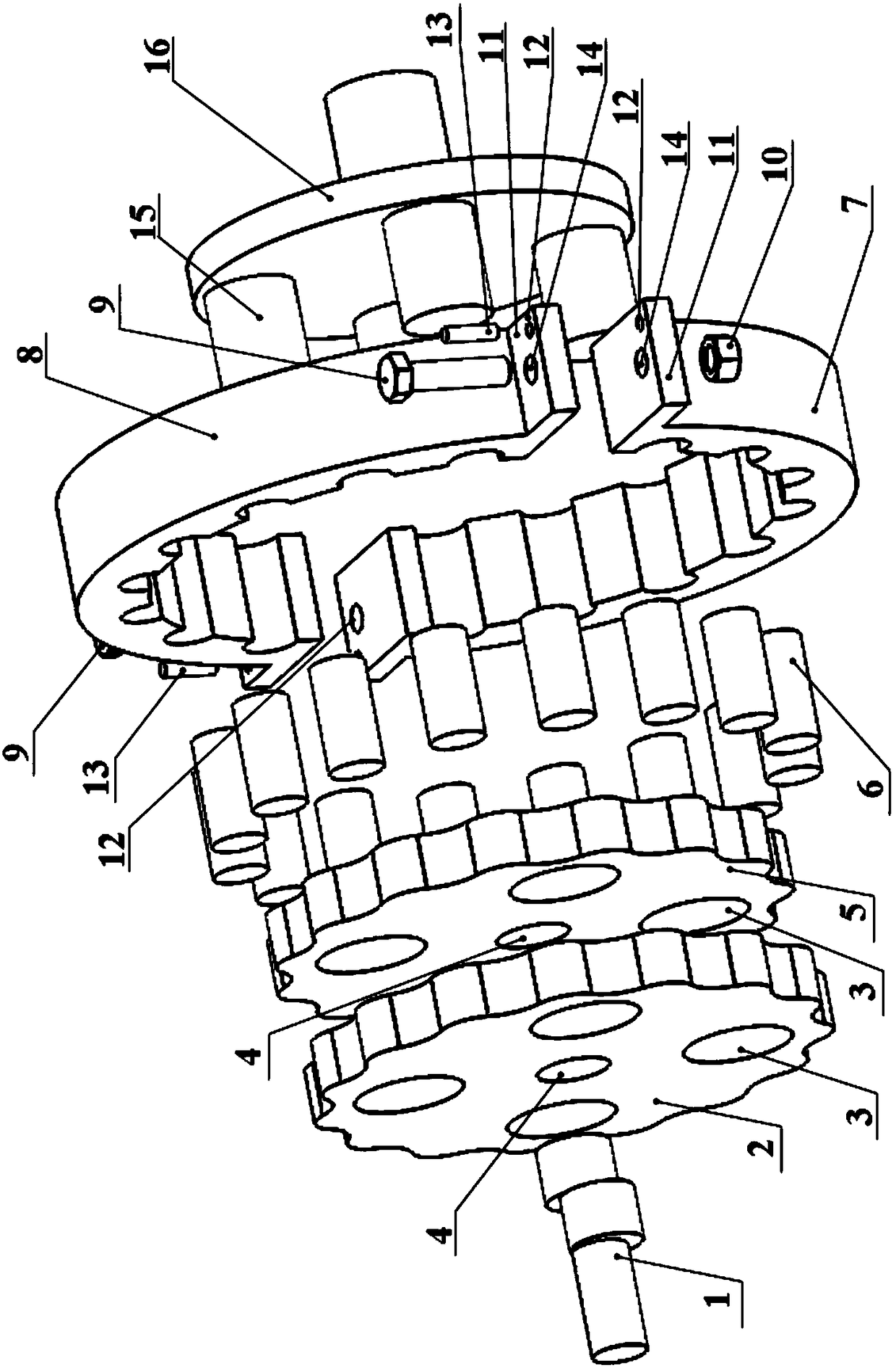
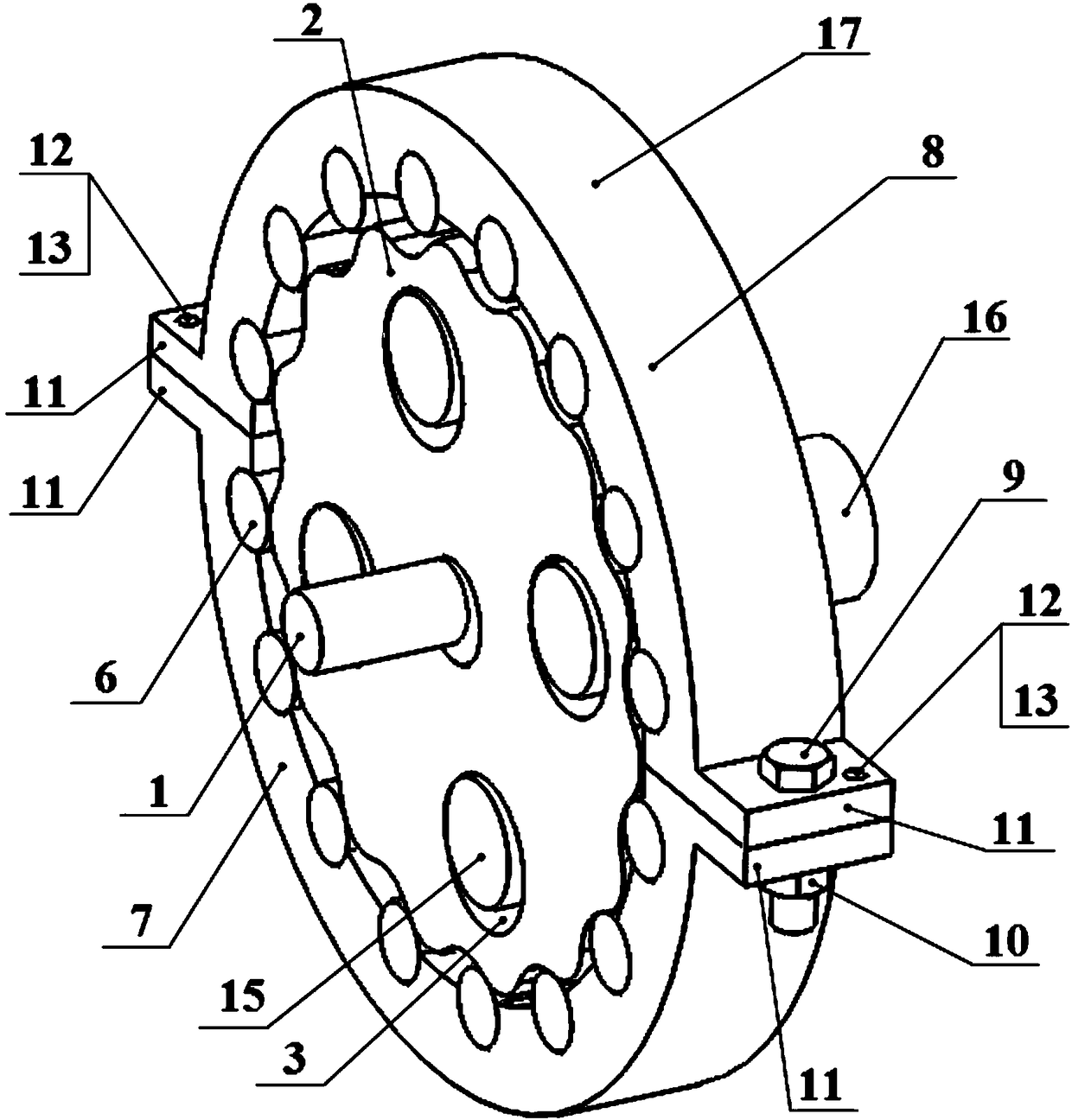
[0028] A cycloid reducer of this embodiment, such as figure 1 , figure 2 As shown, it includes input shaft 1, cycloid wheel A2, pin hole 3, center hole 4, cycloid wheel B5, needle roller 6, sub pin wheel A7, sub pin wheel B8, fastening bolt 9, fastening nut 10, Boss 11, positioning pin hole 12, positioning pin 13, through hole 14, bearing pin 15, output disc 16. Described needle wheel 17 is split type, and it is that two completely identical sub-pin wheels A7 and sub-pin wheel B8 are spliced ​​to form complete pin-wheel structure by circumferential angle of 180 °; The wheel 17 meshes with the cycloid wheel B5 through the needle roller 6, and the mating surface between the two sub-pin wheels is perpendicular to the cross section of the pin wheel. The fixing mechanism for realizing the splicing and splitting of the sub-pin wheels is that the outer sides of the arc end faces of the two sub-pin wheels are provided with bosses 11, and there are through holes 14 at the positions ...

Embodiment 2

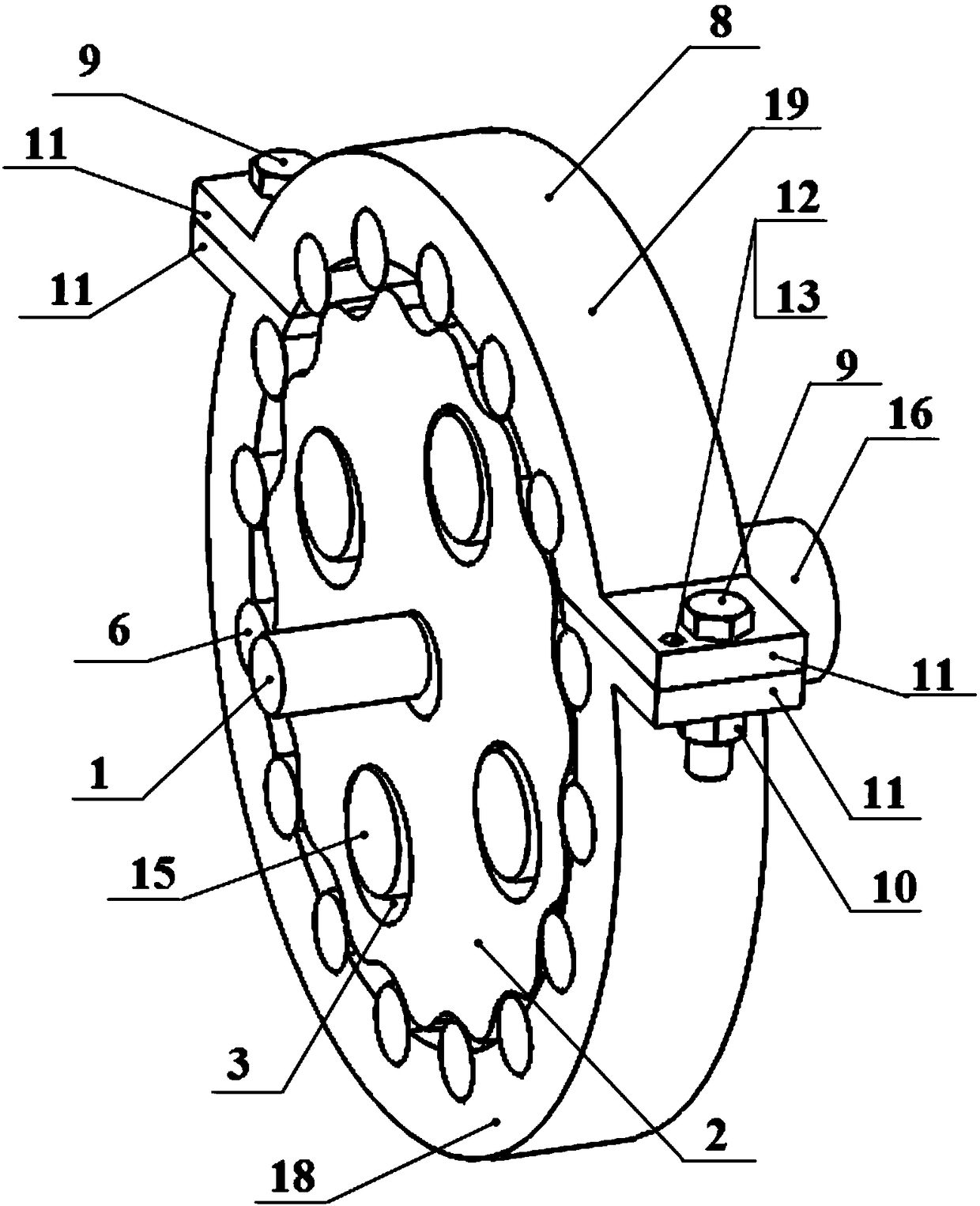
[0032] Such as image 3 As shown, the needle wheel 17 of the present embodiment is composed of two arc-shaped sub-pin wheels C18 and sub-pin wheels D19 splicing to form a complete pin-wheel structure; the circumferential angles of the two sub-pin wheels are respectively 60° and 120°; the pin wheel 17 meshes with the cycloid wheel B5 through the needle roller 6; the mating surface between the sub-pin wheels is perpendicular to the cross section of the pin wheel, and other fixed mechanisms that realize the splicing and splitting of the sub-pin wheels, The positioning, connection and fastening methods and the working principle of the reducer are the same as those in Embodiment 1.

Embodiment 3

[0034] The decomposition structure of the pin wheel in this embodiment is as follows: Figure 4 As shown, the sub-pin wheel adopts the cone surface positioning method, and its connection relationship is as follows: a convex cone 20 is provided on the lower surface of the boss 11 of the sub-pin wheel A7, and a convex cone 20 is provided on the corresponding position of the boss 11 of the other sub-pin wheel B8. A concave cone 21 is provided, and the two sub-pin wheels are butted together, and the conical surfaces between the convex cone 20 and the concave cone 21 cooperate with each other to realize the positioning of the two sub-pin wheels. The working principles of other fixing mechanisms, connection and fastening methods and speed reducers for realizing the splicing and dismantling of the sub-pin wheels are the same as those in Embodiment 1.


PUM


Abstract

The invention discloses a cycloidal-pin gear speed reducer which comprises an input shaft, a cycloidal gear, a pin gear and an output plate, and is characterized in that the pin gear is split-type; anintegrated pin gear structure is formed by splicing a plurality of sub pin gears of which the sum of the angles of circumference is 360 degrees; the matching surfaces between the adjacent sub pin gears is perpendicular or not perpendicular to the cross section of the pin gear; the sub pin gears are engaged with the cycloidal gear through rolling needles; and a fixed connection mechanism realizingsplicing and splitting of the sub pin gears is arranged on the circular arc-shaped end surface of each sub pin gear. The cycloidal-pin gear speed reducer has the advantages that the defects of a cycloidal-pin gear speed reducer which is of an integrated pin gear structure is overcome, the lubricating effect is effectively improved, the friction force is reduced, and the service lives of all components in the speed reducer are prolonged; positioning, fastening and dismounting modes are diversified, the replacement of rolling needles is facilitated, and the worn sub pin gears can be only replaced; and the production cost is effectively reduced, the production efficiency is improved, and the practicability is high.

Description

technical field [0001] The invention relates to a mechanical transmission device, in particular to a reducer, in particular to a cycloidal pinwheel reducer. Background technique [0002] With the development of industrial technology, factory automation and intelligence have higher and higher performance requirements for mechanical equipment transmission. The development trend of the reducer is towards high precision, light weight, high load capacity and miniaturization. At present, there are many types of reducers on the market, including common planetary reducers, gear reducers, cycloid reducers, etc. As a new type of structure, the cycloidal pin gear reducer is a planetary gear transmission with a small tooth difference. It has multiple teeth engaged in meshing at the same time. With many advantages, it is widely used in mining, metallurgy, chemical industry, national defense, lifting and transportation and other industries. At present, the structure of most cycloid red...

Claims


Application Information

Patent Timeline
Patent Type & Authority Applications(China)
IPC IPC(8): F16H1/32F16H57/023
CPCF16H1/32F16H57/023
Inventor 宋雷邵明郑振兴余熳烨梁顺可
Owner GUANGDONG POLYTECHNIC NORMAL UNIV
Why Eureka
Try Eureka