Light driven ultrasonic probe and ultrasonic imaging system thereof

An ultrasonic probe and light-driven technology, which is applied in the direction of using wave/particle radiation devices to transmit sensing components, can solve line crosstalk, difficulty in selecting ultrasonic transducers, and piezoelectric transducers that do not have high-frequency parts for receiving ultrasonic waves. Information capacity and other issues to achieve the effect of expanding the scope

Active Publication Date: 2019-01-04
INST OF ELECTRICAL ENG CHINESE ACAD OF SCI
View PDF14 Cites 7 Cited by
  • Summary
  • Abstract
  • Description
  • Claims
  • Application Information

AI Technical Summary

Problems solved by technology

[0006] In addition, the photoinduced ultrasonic transducers or photoacoustic probes currently designed and developed are only light-driven ultrasonic transducer devices based on a single mode of ultrasonic emission, and the reception of ultrasonic echoes still requires the use of piezoelectric ultrasonic probes with high-frequency bandwidth capabilities. On the contrary, the whole ultrasound imaging system becomes extremely complex and huge
[0007] For example, when using a high-frequency piezoelectric ultrasonic probe to receive ultrasonic echoes, it is necessary to solve the problem of matching the bandwidth of the photoacoustic transducer with a single emission ultrasonic mode. A piezoelectric transducer with a low bandwidth does not have a high-frequency part for receiving ultrasonic waves. The abi

Method used


Image

  • Light driven ultrasonic probe and ultrasonic imaging system thereof
  • Light driven ultrasonic probe and ultrasonic imaging system thereof
  • Light driven ultrasonic probe and ultrasonic imaging system thereof

Examples


Embodiment Construction

[0038] The present invention will be further described below in conjunction with the accompanying drawings and specific embodiments.

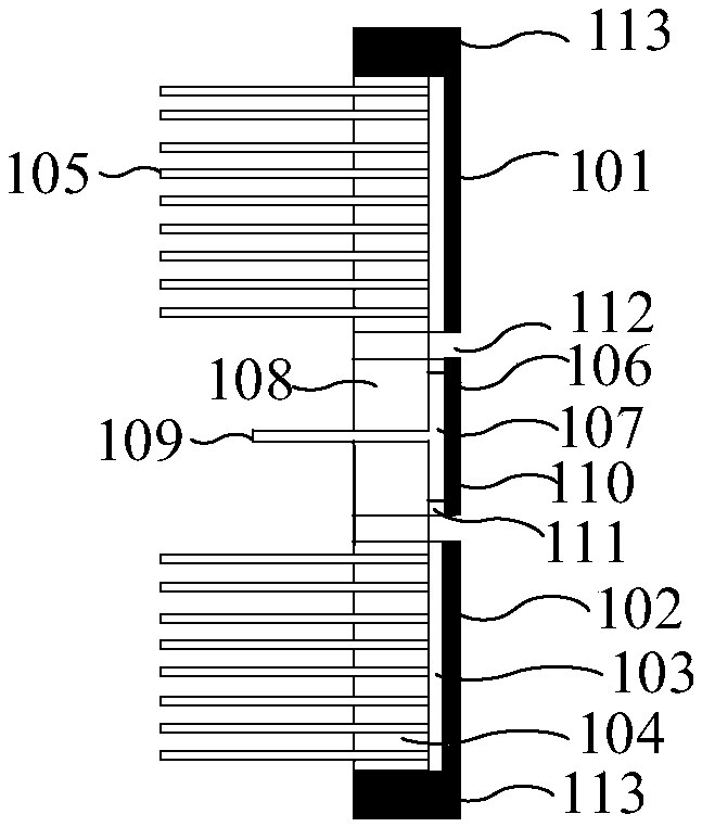
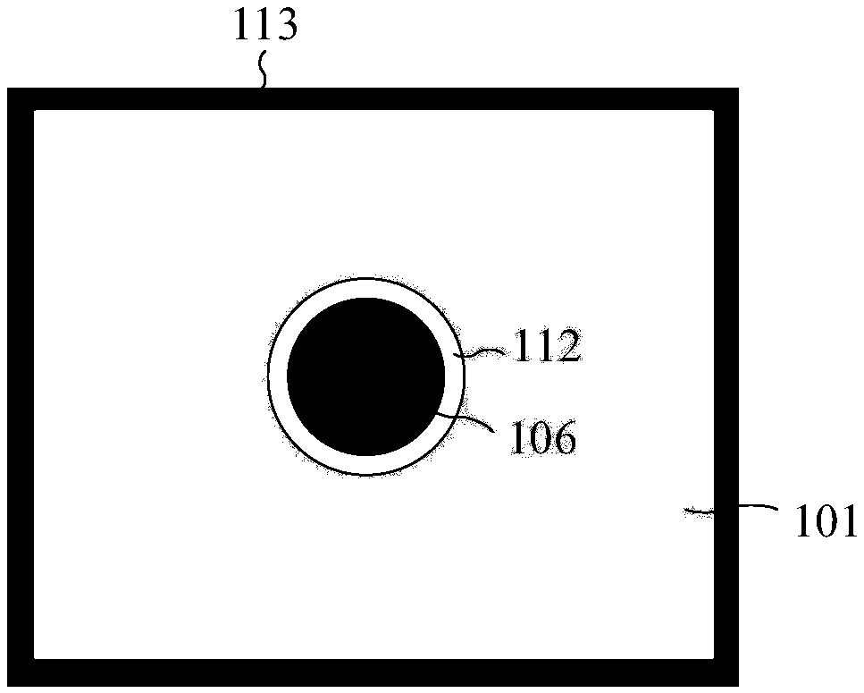
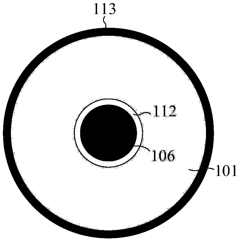
[0039] The light-driven ultrasound probe 204 of the present invention is composed of a photoacoustic emitter 101 for emitting ultrasound and a Fabry-Perot (F-P) cavity 106 for receiving ultrasound. A Fabry-Perot (F-P) cavity 106 is located in the center of the photoacoustic emitter 101 .

[0040] The upper surface of the Fabry-Perot (F-P) cavity 106 and the upper surface of the photoacoustic emitter 101 together constitute the front end of the light-driven ultrasonic probe 204 .

[0041] As shown in FIG. 1 , the ultrasonic transmitter 101 includes a photoacoustic conversion film 102 and a transparent substrate 103 . The photoacoustic conversion film 102 is coated on the upper surface of the transparent substrate 103 , and the lower surface of the transparent substrate 103 is welded to the front surface of the support base 104 made of glass. T...


PUM


Abstract

The invention relates to a light driven ultrasonic probe and an ultrasonic imaging system thereof. A Fabry-Perot (F-P) cavity (106) which receives ultrasonic signals is positioned in the center of anphoto-acoustic emitter (101). The photo-acoustic emitter (101) comprises a photo-acoustic conversion film (102) generating ultrasound, a transparent substrate (103), and a support pedestal (104) whichsupporting the photo-acoustic conversion film (102) and the transparent substrate (103). The upper surface of the transparent substrate (103) is coated with the photo-acoustic conversion film (102),and the lower surface of the transparent substrate (103) is welded to the front surface of the support pedestal (104). A light absorption layer and a thermo-elastic layer are deposited successively inthe upper surface of the transparent substrate. The ultrasonic imaging system of the light driven ultrasonic probe is used to convert an array pulse laser beam into pulse ultrasound, and radiate theultrasound on a target. Ultrasonic echoes reflected from the target reaches the F-P cavity of the light driven ultrasonic probe, detection laser enters the head of the F-P cavity, and cavity length change caused by ultrasonic pressure of the F-P cavity is detected.

Description

technical field [0001] The invention relates to an ultrasonic phased array probe and an ultrasonic imaging system thereof. Background technique [0002] Ultrasonic technology is widely used in industrial non-destructive testing, medical diagnosis and treatment, underwater communication and positioning, material testing and analysis, and plays an important role in social life and industrial production. At present, ultrasound is mainly generated by electrically driven ultrasonic transducers, which are devices that convert electrical energy into acoustic energy. According to the principle of energy conversion and the different materials used, they can be divided into piezoelectric type, capacitive, mechanical, and magnetostrictive transducers. In recent years, phased array ultrasonic medical detection has been widely developed and applied. Since phased array ultrasonic does not require complex mechanical scanning devices, it can flexibly and effectively control the sound beam,...

Claims


Application Information

Patent Timeline
IPC IPC(8): G01D5/48
CPCG01D5/48
Inventor 丁广鑫夏慧李晓南王丽丽
Owner INST OF ELECTRICAL ENG CHINESE ACAD OF SCI
Why Eureka
Try Eureka