High-temperature high-pressure solid-containing multi-phase particle erosive wear testing device

A wear test, high temperature and high pressure technology, applied in the field of erosion wear devices, can solve the problems of unknown erosion speed, uneven mixing of erosion particles and gas, and inaccuracy, so as to meet emission requirements, save experimental time, and improve uniformity. sexual effect

Inactive Publication Date: 2019-01-04
NANJING UNIV OF SCI & TECH
View PDF8 Cites 9 Cited by
  • Summary
  • Abstract
  • Description
  • Claims
  • Application Information

AI Technical Summary

Problems solved by technology

However, the research in this area in our country started relatively late, especially the erosion test methods and equipment under high temperature conditions are not perfect enough, and the traditional abrasive wear test at room temperature is still used in the design of erosion-resistant wear coatings, which cannot simulate Real working conditions of high temperature erosion
For example, the vacuum drop test device is only suitable for low-speed tests (the speed is generally less than 5m/s); the centrifugal abrasive acceleration test device has the disadvantages that the speed and angle are not suitable for precise control; The impact speed is caused by mechanical rotation, so it is very important to control the constant speed of the motor; th

Method used


Image

  • High-temperature high-pressure solid-containing multi-phase particle erosive wear testing device
  • High-temperature high-pressure solid-containing multi-phase particle erosive wear testing device
  • High-temperature high-pressure solid-containing multi-phase particle erosive wear testing device

Examples


Embodiment Construction

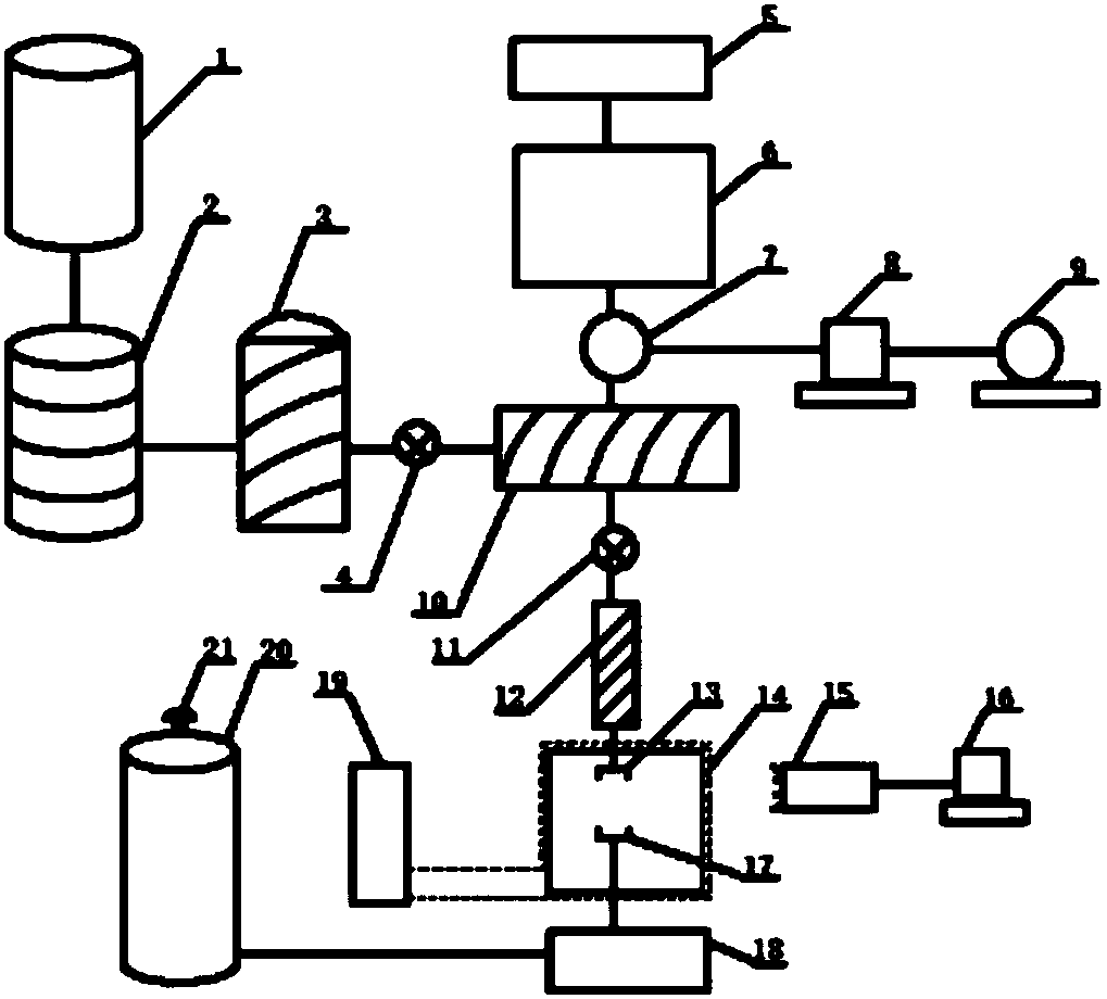
[0025] The present invention will be further described below in conjunction with accompanying drawing.

[0026] Such as figure 1 , figure 2 , image 3 Shown, the structure of the present invention is: air compressor 1 links to each other with air drier 2 and high-temperature air heater 3 through pipeline, the outlet of high-temperature air heater connects gas flowmeter and pressure tester 4, particle size screening machine 5 and The solid particle heating chamber 6 is connected to the particle mixing auxiliary heating chamber 10. The falling of the solid particles is controlled by the impeller feeder 7. The impeller feeder is controlled by the reducer 8 and the governor 9. The particle mixing auxiliary heating chamber passes through the solid flow The meter 11 and the acceleration pipeline 12 are connected with the box body 14. The air heated in the high-temperature air heater passes through the gas flow meter and mixes with the solid particles in the particle mixing auxili...


PUM


Abstract

The invention discloses a high-temperature high-pressure solid-containing multi-phase particle erosive wear testing device which comprises an air heating device, a gas-solid mixing device, a wear simulating device and a tail gas dust removal device. An air compressor is connected with an air dryer, a high-temperature air heater, a gas flow meter and a pressure intensity tester. The gas flow meteris connected with a particle mixing and auxiliary heating chamber. A mixing and heating chamber is connected with a solid particle heating chamber and a particle size screening machine. Solid particles are controlled by an impeller feeder to fall. An outlet of the mixing and heating chamber extends into a tank body through a solid flow meter and an acceleration pipeline. The tank body is controlled by a surrounding water cooling system to be cooled and is internally provided with a porous nozzle and a sample supporting frame. A sample heater is arranged on the sample supporting frame. A water-cooled sedimentation type dust collector is connected with the bottom of the tank body. A doppler laser velocimeter is aligned with a to-be-tested material in the tank body. By means of the testing device, the movement conditions and erosive wear conditions of solid-containing multi-phase particles hit on the material under different temperatures and pressure intensities can be researched.

Description

technical field [0001] The invention relates to an erosion wear device, in particular to a high temperature and high pressure solid-containing multiphase particle erosion wear test device. Background technique [0002] Erosion wear is one of the main wear forms of material damage, accounting for about 8% of the total number of wear damage in industrial production. It refers to the impact of fluid or solid particles on the material surface at a certain speed and angle at a certain speed and angle. caused wear and tear. The high-temperature erosion and wear damage is particularly serious. The life of the helicopter engine is also shortened by 90% due to the erosion caused by the inhalation of dust. There are also rocket nozzle throat linings and gas turbine engines that use pulverized coal as fuel. All suffer from severe high temperatures. The damage of erosion and wear, more than one-third of the coal-fired boiler pipeline accidents in power stations are caused by erosion an...

Claims


Application Information

Patent Timeline
IPC IPC(8): G01N3/02G01N3/56
CPCG01N3/02G01N3/565G01N3/567
Inventor 熊党生刘宇豪李建亮闫成旗
Owner NANJING UNIV OF SCI & TECH
Why Eureka
Try Eureka