
Lightning positioning system based on VHF radar and lightning positioning method

A lightning positioning system and lightning positioning technology, applied in the field of lightning detection, can solve the problems of low measurement accuracy of the system, unsatisfactory positioning effect of narrow-band interference technology, construction of selected points and stations, and inconvenient investment and operation management of high-precision time synchronization equipment. problems, to achieve the effect of improving adaptability

Pending Publication Date: 2019-01-04
WUHAN UNIV
View PDF7 Cites 15 Cited by
  • Summary
  • Abstract
  • Description
  • Claims
  • Application Information

AI Technical Summary

Problems solved by technology

In the case of multiple radiation sources, the positioning effect of narrowband interferometry technology is not satisfactory; although broadband interferometer technology can locate multiple radiation sources, the system measurement accuracy is relatively low
[0006] To sum up, it can be seen that the existing two VHF radiation source location technologies based on time difference and phase difference need to adopt the multi-station form for lightning location, that is, the form of multiple radar echo receiving stations, and two or two The lightning positioning of the above receiving stations will bring a lot of inconveniences in site selection, station construction, high-precision time synchronization, equipment investment and operation management, which will lead to the poor adaptability of the lightning positioning system

Method used


Image

  • Lightning positioning system based on VHF radar and lightning positioning method
  • Lightning positioning system based on VHF radar and lightning positioning method
  • Lightning positioning system based on VHF radar and lightning positioning method

Examples


Embodiment 1

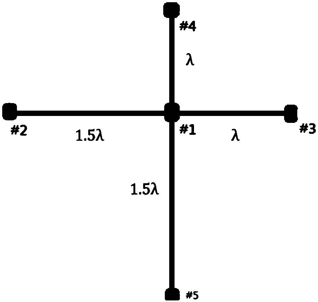
[0061] In specific implementation, such as figure 1 As shown in FIG. 1 , it is a schematic structural diagram of an interference receiving antenna in a VHF radar-based lightning locating system provided in Embodiment 1. The interference receiving antenna contains at least two long baseline antenna arrays and at least two short baseline antenna arrays; the long baseline antenna array contains at least two receiving antennas; the short baseline antenna array contains at least two receiving antennas, and the endpoints of the long baseline antenna arrays are connected to The endpoints of the short baseline antenna array are provided with common receive antennas.

[0062] The distance between two adjacent receiving antennas in the long baseline antenna array is greater than the distance between two adjacent receiving antennas in the short baseline antenna array; and the size of the receiving antenna is similar to the wavelength of the VHF radar wave emitted by the VHF radar transmi...

Embodiment 2

[0126] Embodiment 2 provides a lightning location method based on VHF radar. Figure 10 A schematic flow chart of a VHF radar-based lightning location method provided in Embodiment 2, such as Figure 10 As shown, the method includes:

[0127] S1101: Sending VHF radar waves to the lightning, receiving VHF radar echoes reflected by the plasma surface where the lightning is located; measuring the phase at which the VHF radar echoes reach each receiving antenna.

[0128] Specifically, it is possible to send VHF radar waves to the lightning at least twice, and receive the VHF radar echoes reflected each time from the plasma surface where the lightning is located, and the power of the VHF radar waves emitted each time is different; according to the VHF radar echoes and The power difference between the lightning radiated electromagnetic waves identifies the VHF radar echo and measures the phase at which the VHF radar echo reaches each receiving antenna.

[0129] Exemplarily, the VH...

Embodiment 3

[0222] Such as Figure 13 As shown, it is a schematic diagram of the relative position of lightning relative to the receiving antenna in a lightning location method based on VHF radar provided in Embodiment 3, as shown in Figure 13 As shown, the distance between the lightning and the first receiving antenna #1 is R 1 ; The distance between the lightning and the second receiving antenna #2 is R 2 ; The distance between the lightning and the third receiving antenna #3 is R 3 ; The distance between the lightning and the fourth receiving antenna #4 is R 4 ; The distance between the lightning and the fifth receiving antenna #5 is R 5 .

[0223] The specific structure of the receiving antenna is as follows figure 1 As shown, #1 and #2 receive antennas, with a distance of 1.5λ to form a long baseline antenna array-1, #1 and #5 receive antennas with a distance of 1.5λ to form a long baseline antenna array-2; #1 and #3 receive antennas with a distance of 1λ to form a The short b...


PUM


Abstract

The invention relates to the technical field of lightning detection, in particular to a lightning positioning system based on a VHF radar and a lightning positioning method. The lightning positioningsystem comprises a VHF radar transmitting system and a radar receiving system arranged in the same station. The radar receiving system comprises an interference receiving antenna comprising at least two long baseline antenna arrays and at least two short baseline antenna arrays. Each of the long baseline antenna arrays and the short baseline antenna arrays comprises at least two pairs of receivingantennas. Terminals of the long baseline antenna arrays and the short baseline antenna arrays are provided with public receiving antennas. A distance between the adjacent two pairs of receiving antennas in each long baseline antenna array is greater than that of the adjacent two pairs of receiving antennas in each short baseline antenna array. The size of the receiving antennas is matched with the wavelength of VHF radar waves transmitted by means of a VHF radar transmission system. The positioning system can realize three-dimensional positioning of lightning and single-station positioning oflightning.

Description

technical field [0001] The invention belongs to the technical field of lightning detection, in particular to a VHF radar-based lightning location system and a lightning location method. Background technique [0002] Lightning is a special weather phenomenon, which refers to the local weather accompanied by lightning activity and short-term precipitation caused by cumulonimbus clouds; in ground observation, it refers to the weather phenomenon accompanied by lightning and thunder as a local Severe convective weather often causes losses in personnel and economic property. Lightning disaster has become one of the ten most serious natural disasters announced by the United Nations. It has the characteristics of semi-randomness, dispersion, locality, instantaneousness, suddenness and three-dimensionality. [0003] At present, lightning VHF (Very High Frequency, very high frequency) radiation detection system is commonly used to locate lightning. Almost the entire lightning discha...

Claims


Application Information

Patent Timeline
Patent Type & Authority Applications(China)
IPC IPC(8): G01S13/42G01S13/95
CPCG01S13/42G01S13/95Y02A90/10
Inventor 周晨赵正予青海银章无用
Owner WUHAN UNIV
Learn More