A light source system and a projection system applying the same

A technology of a light source system and a relay system, applied in the field of projection systems, can solve the problems of low light conversion efficiency of red phosphors, high price, long back focal length of the projection lens, etc., so as to improve the utilization rate of light energy, reduce the difficulty, and achieve a compact structure. Effect

Active Publication Date: 2019-01-04
APPOTRONICS CORP LTD
View PDF5 Cites 3 Cited by
  • Summary
  • Abstract
  • Description
  • Claims
  • Application Information

AI Technical Summary

Problems solved by technology

Red, green, and blue phosphors are coated on the color wheel to obtain the three primary colors of red, green, and blue light. However, the light conversion efficiency of red phosphors is low, resulting in the use of single-chip spatial light modulation projection The image brightness of the red light part of the system is low, which affects the overall image display effect
Due to t

Method used


Image

  • A light source system and a projection system applying the same
  • A light source system and a projection system applying the same
  • A light source system and a projection system applying the same

Examples


Embodiment Construction

[0019] The following will clearly and completely describe the technical solutions in the embodiments of the present invention with reference to the accompanying drawings in the embodiments of the present invention. Obviously, the described embodiments are only some, not all, embodiments of the present invention. Based on the embodiments of the present invention, all other embodiments obtained by persons of ordinary skill in the art without making creative efforts belong to the protection scope of the present invention.

[0020] Unless otherwise defined, all technical and scientific terms used herein have the same meaning as commonly understood by one of ordinary skill in the technical field of the invention. As used herein, the term "or / and" includes any and all combinations of one or more of the associated listed items.

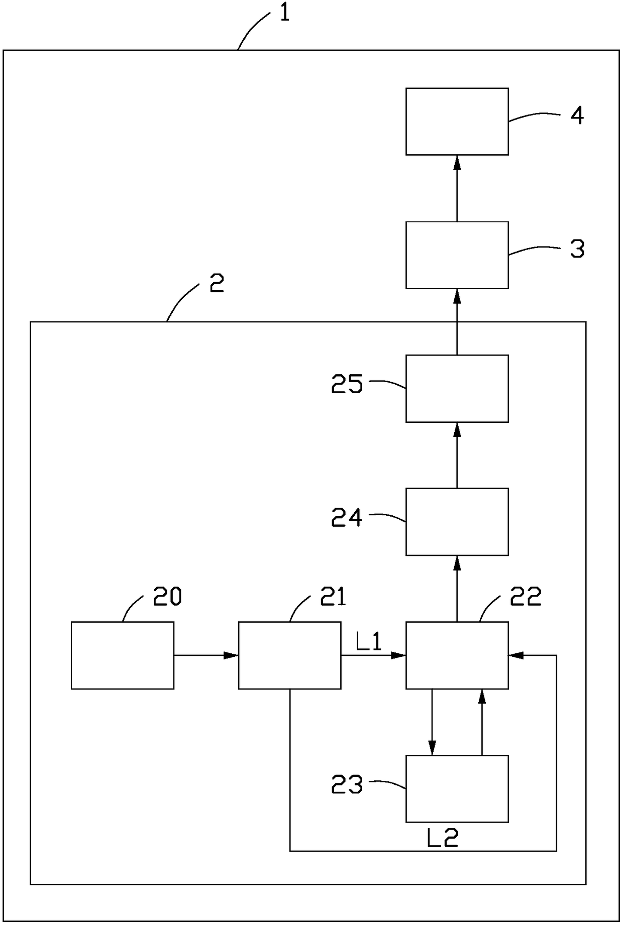
[0021] see figure 1 Shown is a schematic block diagram of the first embodiment of the projection system of the present invention. The projection system 1 ...


PUM


Abstract

The invention relates to a light source system and a projection system. The light source system includes a light emitting unit, optical path switching unit, wavelength conversion unit, and first and second beam splitting units, wherein the light emitting unit emits a light beam, the optical path switching unit switches the light beam emitted by the light emitting unit into a first optical path ora second optical path, the first beam splitting units are arranged at the tail ends of the first optical path and the second optical path and used for guiding incident beams to the wavelength converting unit or second beam splitting unit, the first beam splitting units are further configured to guide the light beam emitted by the wavelength converting unit after wavelength conversion to the secondbeam splitting unit, the second beam splitting unit is used for sequentially emitting the incident beams after splitting, and the second optical path passes through between the wavelength convertingunit and the first beam splitting unit, and the height of the second optical path in at least one dimension direction is lower than that of the wavelength converting unit in the dimension direction. By using the invention, the light energy utilization rate is high and the structure is compact.

Description

technical field [0001] The invention relates to the field of projection display, in particular to a light source system and a projection system using the light source system. Background technique [0002] The current projection system using a single-chip spatial light modulator generally uses an excitation light source to irradiate the rotating color wheel to form the three primary colors of red, green, and blue that are emitted sequentially, and the three primary colors of red, green, and blue that are emitted sequentially The light is projected onto the spatial light modulator for modulation, and the modulated monochromatic light images are quickly alternately switched on the screen, and then the monochromatic light images of each sequence are mixed together to form a color image by using the residual visual effect of the human eye. Red, green, and blue phosphors are coated on the color wheel to obtain the three primary colors of red, green, and blue light. However, the li...

Claims


Application Information

Patent Timeline
IPC IPC(8): G03B21/20G02B27/10
CPCG02B27/1006G03B21/204G03B21/2066G03B21/208G02B27/10G02B27/18G03B21/20
Inventor 侯海雄胡飞李屹
Owner APPOTRONICS CORP LTD
Why Eureka
Try Eureka