Motorized joint for programmable moving machine

A mobile and maneuverable technology, applied in the direction of program-controlled manipulators, manipulators, manufacturing tools, etc.

Inactive Publication Date: 2019-01-04
OVALO
View PDF9 Cites 2 Cited by
  • Summary
  • Abstract
  • Description
  • Claims
  • Application Information

AI Technical Summary

Problems solved by technology

[0005] It has been recognized with the invention that the articulation of the programmable robot system known from the patent document US 8,614,559 B2 mentioned at the outset has the disadvantage that the drive rotation of the drive motor cannot be reliably performed by means of a safety brake in any case be banned

Method used


Image

  • Motorized joint for programmable moving machine
  • Motorized joint for programmable moving machine

Examples


Embodiment Construction

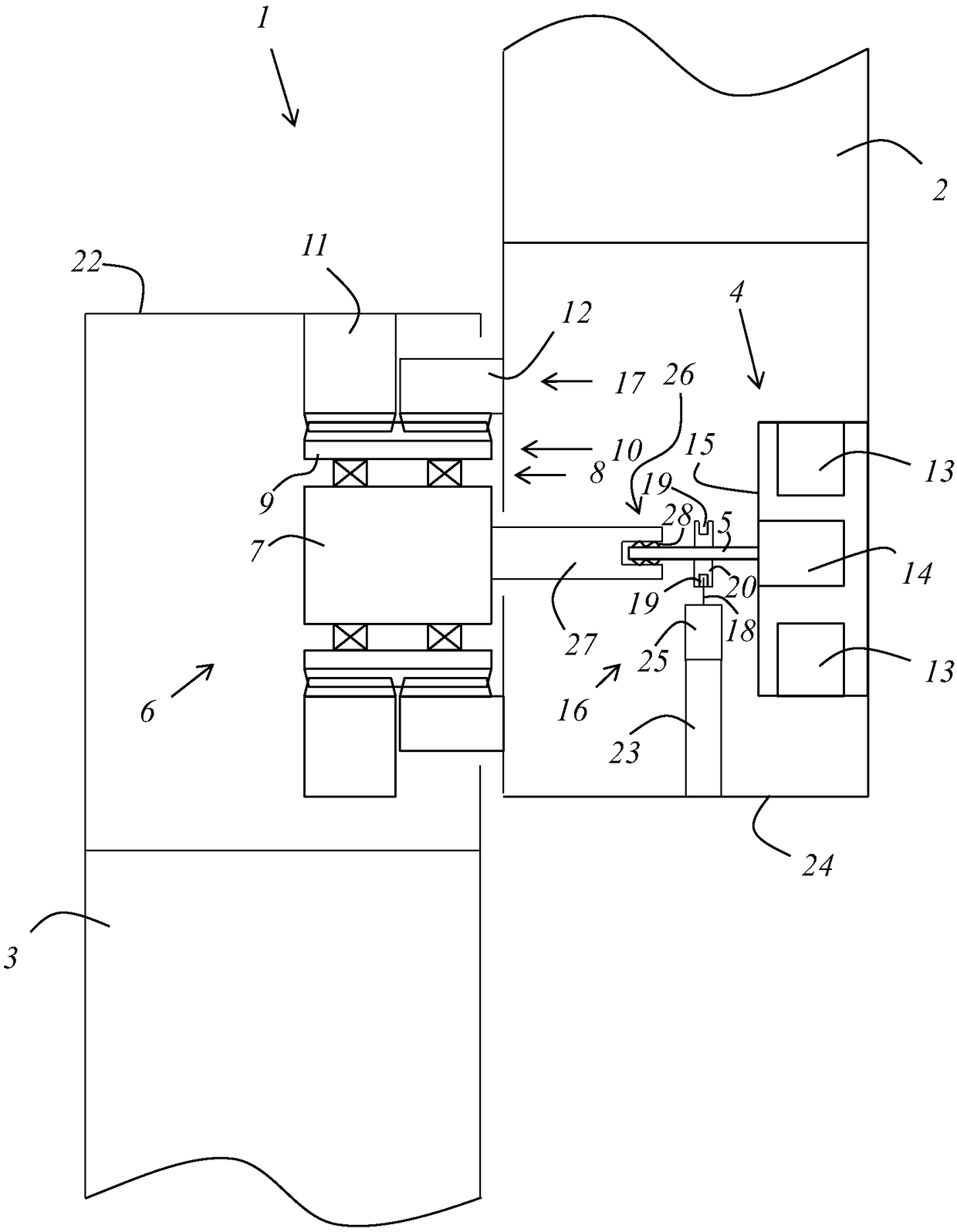
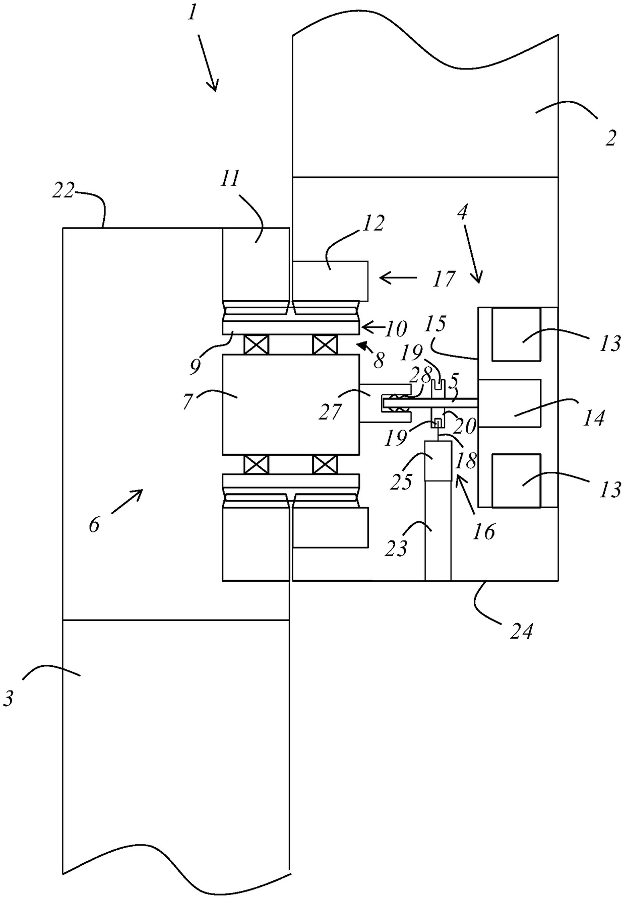
[0031] figure 1 A first exemplary embodiment of a motorized joint 1 for articulated connection of a first support 2 and a second support 3 of a programmable robot is shown. The motorized joint 1 contains a drive motor 4 with a driven shaft 5 and a transmission 6 downstream of the drive motor 4 in terms of transmission. The transmission 6 is designed as a stress wave transmission.

[0032] The motorized joint 1 has a first housing part 24 and a second housing part 22 . The first housing part 24 is rigidly connected to the first carrier 2 , while the second housing part 22 is rigidly connected to the second carrier 3 . Alternatively, it is also possible that the housing of the first support additionally also serves as the first housing part 24 and / or that the housing of the second support additionally also serves as the second housing part 22 .

[0033] In this exemplary embodiment, the drive motor 4 is arranged in the first housing part 24 and the gear mechanism 6 is arrange...


PUM


Abstract

The invention relates to a motorized joint (1) for connecting two supports (2, 3), which can be moved relative to each other, of a programmable moving machine having a drive motor (4); a transmission(6) which is drivingly connected downstream of the drive motor (4); and a securing device (16). The motorized joint (1) is characterized in that the securing device (16) is designed and arranged to directly lock an output shaft (5) of the drive motor (4) or a blocking means (20) which is rotationally fixed to the output shaft (5) of the drive motor (4), and the output shaft (5) is rotationally fixed to a driveshaft (27) of the transmission (6) by means of a connection coupling (26). The connection coupling (26) allows a movement of the output shaft (5) relative to the driveshaft (27) when a torque over a specified or specifiable value occurs between the output shaft (5) of the drive motor (4) and the driveshaft (27) of the transmission (6).

Description

technical field [0001] The invention relates to a motorized joint for connecting two supports movable relative to each other of a programmable automatic mobile machine, the joint has a drive motor and a transmission mechanism connected behind the drive motor in terms of transmission technology and a locking device. Background technique [0002] A programmable robot system is known from US 8,614,559 B2. The robot system contains a robot with a plurality of independent arm sections, wherein adjacent arm sections are each connected to each other by joints. The robotic system also includes a controllable drive in at least one joint and a control system for controlling the drive. The robotic system also has a user interface via which the robotic system can be programmed. The joint has a housing and an electric motor arranged in the housing with a motor shaft that rotates relative to the housing. Also in the housing is a safety catch with a locking catch that can be activated ...

Claims


Application Information

Patent Timeline
Patent Type & Authority Applications(China)
IPC IPC(8): B25J9/12B25J17/02B25J19/00B25J9/10B25J19/06
CPCB25J19/065B25J9/102B25J9/1025B25J9/126B25J17/0241B25J19/0004
Inventor 西格马·吉尔格斯
Owner OVALO
Why Eureka
Try Eureka