Membrane tube type falling film evaporator

A falling film evaporator and evaporator technology, applied in evaporator accessories, evaporation, chemical instruments and methods, etc., can solve the problems of liquid film wetting the inner wall of the evaporation tube, affecting the uniform distribution of liquid film, and mutual interference of liquids, etc., to achieve Good sealing, high connection stability, and the effect of reducing energy loss

Pending Publication Date: 2019-01-08
上海三耕储节能环保科技有限公司
View PDF2 Cites 0 Cited by
  • Summary
  • Abstract
  • Description
  • Claims
  • Application Information

AI Technical Summary

Problems solved by technology

But it still has the following problems: if the tangential holes provided on the draft tube are not enough, the liquid film cannot completely wet the inner wall of the evaporation tube, and too many tangential holes provided on the draft tube will make the tangential holes enter. The liquid interferes with each other, which affects the uniform distribution of the liquid film; the wall thickness of the guide tube is relatively thick, generally 0.5-1.5 mm, and the manufacturing cost is high. The heat exchange occurs only when the temperature difference between the inner and outer media of the guide tube is large, and the heat transfer effect is poor.

Method used


Image

  • Membrane tube type falling film evaporator
  • Membrane tube type falling film evaporator
  • Membrane tube type falling film evaporator

Examples


Embodiment Construction

[0030] The following are specific embodiments of the present invention and in conjunction with the accompanying drawings, the technical solutions of the present invention are further described, but the present invention is not limited to these embodiments.

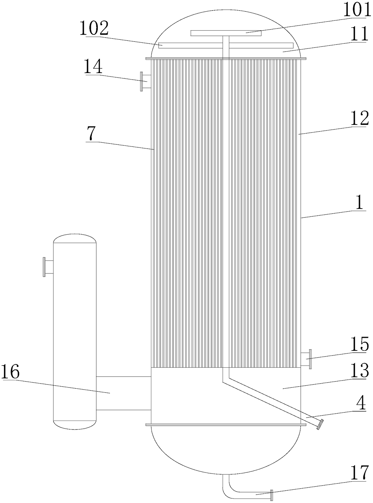
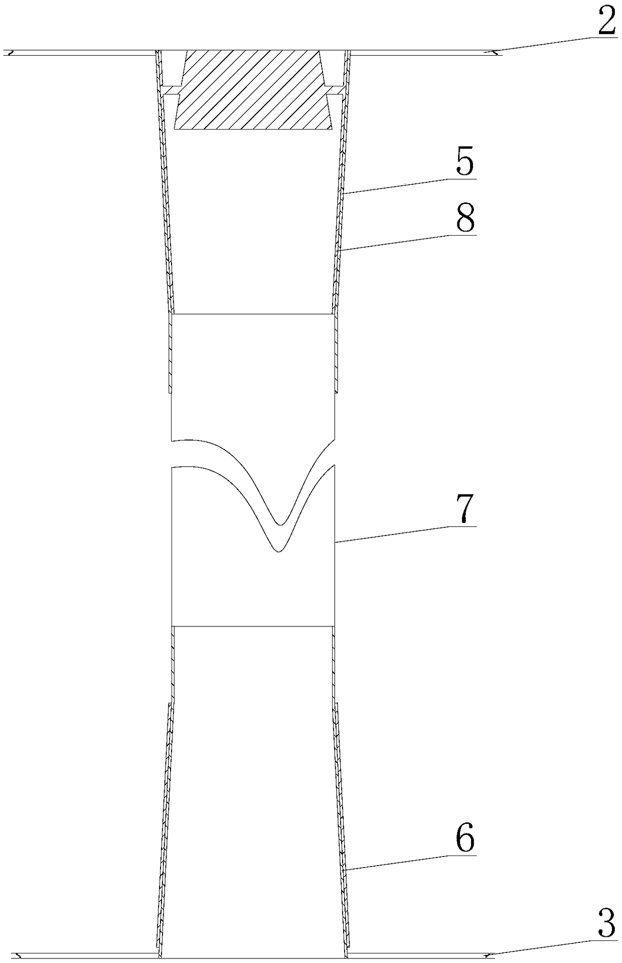
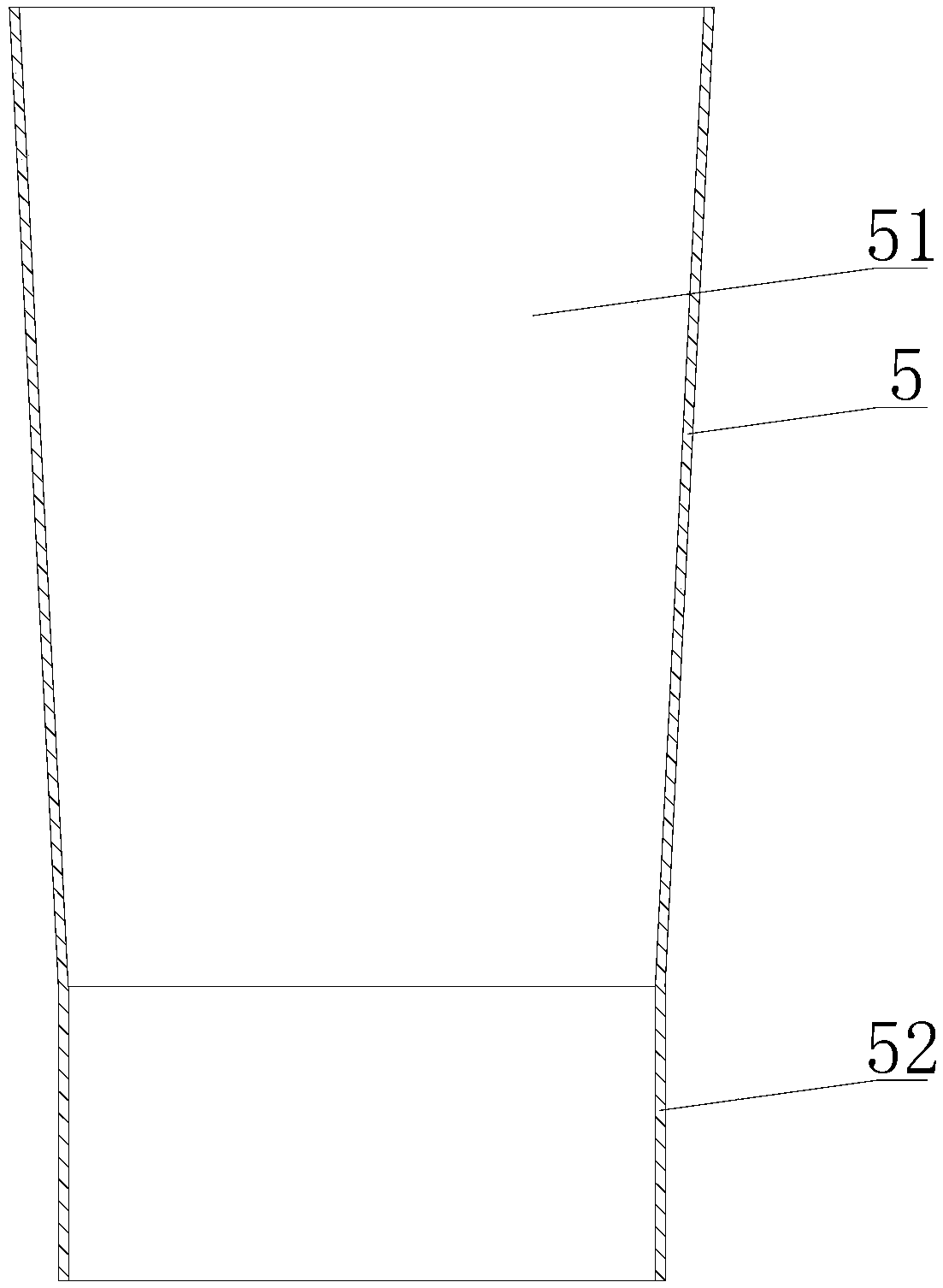
[0031] Such as figure 1 The film tube type falling film evaporator shown includes an evaporator body 1, the evaporator body 1 is provided with an upper partition 2 and a lower partition 3, and the inner cavity of the evaporator body 1 is composed of the upper partition 2 and the lower partition 3 Divided into a liquid inlet chamber 11, a heat exchange chamber 12 and a vapor-liquid separation chamber 13, the evaporator body 1 is provided with a liquid inlet pipe 4 communicating with the liquid inlet chamber 11, and the upper part of the heat exchange chamber 12 is provided with a heating steam inlet 14 , The lower part is provided with a condensed water outlet 15, the upper part of the vapor-liquid separation chamber 13 is ...


PUM

PropertyMeasurementUnit
Thicknessaaaaaaaaaa
Thicknessaaaaaaaaaa

Abstract

The invention provides a membrane tube type falling film evaporator and belongs to the technical field of evaporators. Problems that an existing membrane tube type falling film evaporator is easy to scale and easy to corrode because the existing membrane tube type falling film evaporator is made of metal are solved. The membrane tube type falling film evaporator comprises an evaporator body; an upper partition plate and a lower partition plate are arranged in the evaporator body; a cavity of the evaporator body is divided into a liquid inlet cavity, a heat exchanging cavity and a vapor-liquidseparating cavity by using the upper partition plate and the lower partition plate; a liquid inlet pipe communicated with the liquid inlet cavity is arranged on the evaporator body; a heated vapor inlet is formed in the upper part of the heat exchanging cavity; a condensed water outlet is formed in the lower part of the heat exchanging cavity; a secondary vapor outlet is formed in the upper part of the vapor-liquid separating cavity; a concentrated liquor outlet is formed in the lower part of the vapor-liquid separating cavity; a plurality of upper connecting heads are uniformly distributed onthe upper partition plate; a plurality of lower connecting heads are uniformly distributed on the lower partition plate; the upper connecting heads and the lower connecting heads are communicated with each other through vertical membrane tubes; and a film-distributor is arranged at the upper ends of the vertical membrane tubes. The membrane tube type falling film evaporator provided by the invention has the advantage that the heat exchanging efficiency is effectively enhanced by using the vertical membrane tubes to replace metal tubes while the manufacturing cost is reduced.

Description

technical field [0001] The invention belongs to the technical field of evaporators and relates to a film tube type falling film evaporator. Background technique [0002] Distillation technology is a physical treatment process, which is a separation technology to remove soluble solids from water. Distillation is the only available technique when other wastewater treatment techniques cannot remove soluble solids from the water. Due to the ease of processing of metal materials, most evaporative heat exchangers are made of metal materials, but metal materials are easy to scale and corrode, and need to be cleaned regularly, causing serious secondary pollution; when used in high acid-base and high-salt conditions, evaporation Heat exchangers are made of metals such as stainless steel and titanium, which are extremely expensive. [0003] The falling film evaporator is a kind of efficient evaporation equipment, which belongs to the category of thin film evaporators. For example, ...

Claims


Application Information

Patent Timeline
IPC IPC(8): B01D1/22B01D1/30
CPCB01D1/22B01D1/30
Inventor 邓湘军龚全知
Owner 上海三耕储节能环保科技有限公司
Why Eureka
Try Eureka