Cutting blade with different coatings on rear cutter surface

A technology of cutting inserts and flanks, applied in the attachment of tool holders, tools for lathes, turning equipment, etc., can solve the problems of scrap, low cutting insert service life, mismatched cutting edge life, etc., and achieve extended use. Longevity, improved cost performance, performance optimization and matching effects

Pending Publication Date: 2019-01-08
ZHUZHOU CEMENTED CARBIDE CUTTING TOOLS CO LTD
View PDF6 Cites 2 Cited by
  • Summary
  • Abstract
  • Description
  • Claims
  • Application Information

AI Technical Summary

Problems solved by technology

However, with the rapid development of the metal cutting industry, in order to fully improve the application ability of cutting inserts in certain specific processes, the shapes of the cutting edges in the cutting unit are not exactly the same, and the cutting conditions of each cutting edge are also different. The surface layer of the insert adopts the same surface coating structure. Although the production of the cutting insert is simplified, it is easy to cause the life of each cutting edge in the cutting unit to not match. Scrapping of cutting inserts, lower service life of cutting inserts

Method used


Image

  • Cutting blade with different coatings on rear cutter surface
  • Cutting blade with different coatings on rear cutter surface
  • Cutting blade with different coatings on rear cutter surface

Examples


Embodiment Construction

[0030] The present invention will be further described in detail below in conjunction with the accompanying drawings and specific embodiments.

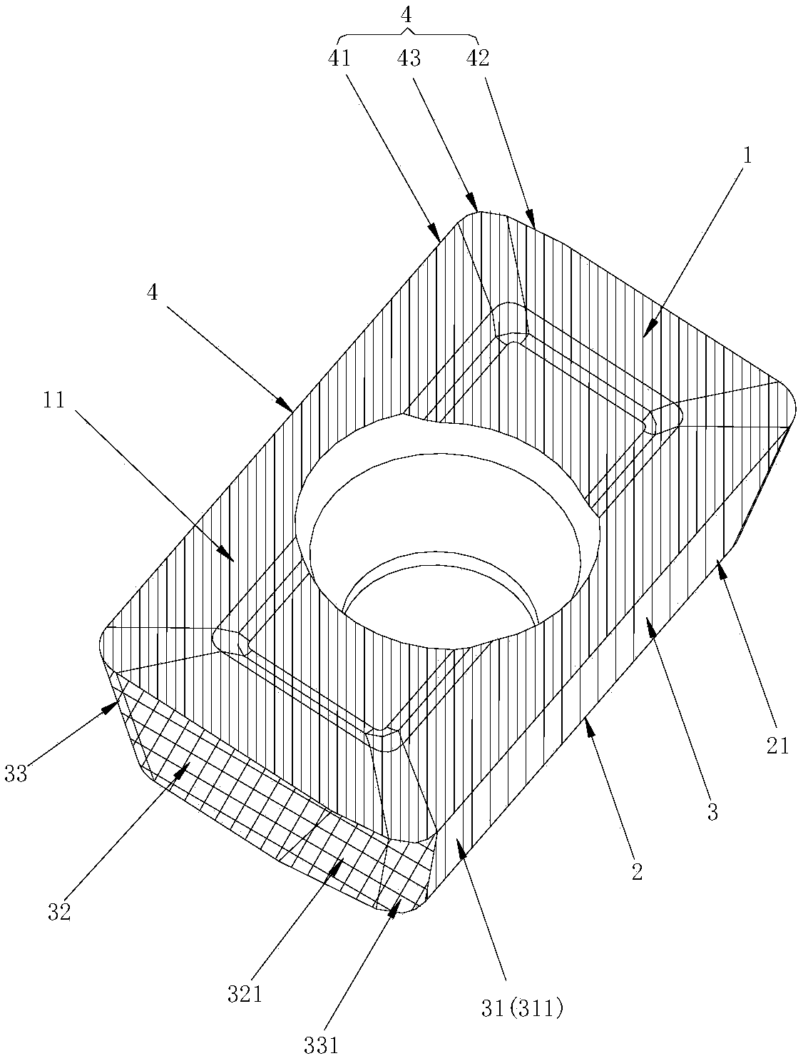
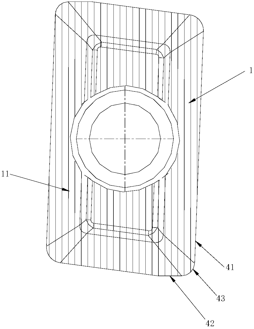
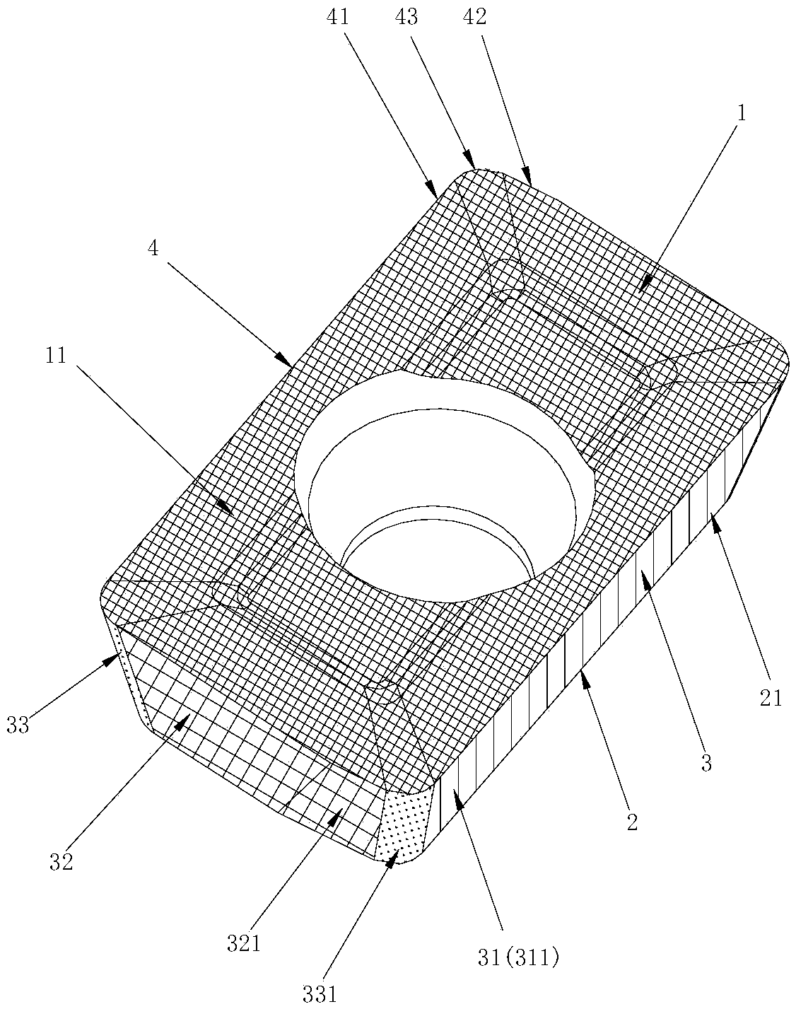
[0031] figure 1 and figure 2 The first embodiment of the cutting insert with different coatings on the flank of the present invention is shown. The cutting insert of this embodiment is surrounded by an upper surface 1, a lower surface 2 and a side surface 3 connecting the upper surface 1 and the lower surface 2, The intersection of the side surface 3 and the upper surface 1 forms more than one set of cutting edge units 4. The cutting edge unit 4 includes adjacent major cutting edges 41, minor cutting edges 42, and corner cutting edges between the major cutting edges 41 and the minor cutting edges 42. Edge 43, side 3 comprises respectively more than a group of primary flanks 31, secondary flanks 32 and angular flanks 33 corresponding to major cutting edges 41, secondary cutting edges 42, and angle cutting edges 43, the primary flanks...


PUM


Abstract

The invention discloses a cutting blade with different coatings on a rear cutter surface. The cutting blade is composed of an upper surface, a lower surface and a side face which is surrounded by theupper surface and the lower surface; the side face and the upper surface intersect to form a group of cutting edge unit or above, and the cutting edge unit comprises an adjacent main cutting edge, anauxiliary cutting edge and an angle cutting edge located between the main cutting edge and the auxiliary cutting edge; the side face comprises one group or above of main rear tool face, auxiliary reartool face and angle rear tool face, and the main rear tool face, the auxiliary rear tool face and the angle rear tool face are corresponding with the main cutting edge, the auxiliary cutting edge andthe angle cutting edge correspondingly; and the main rear tool face and the auxiliary rear tool face are arranged at interval, are provided with a main rear coating layer and an auxiliary rear coating layer correspondingly, and the main rear coating layer and the auxiliary rear coating layer are different in structure and are independent from each other. According to the blade, the cutting bladewith different coatings on the rear cutter face has good cutting performance, long in service life and high in cost performance.

Description

technical field [0001] The invention relates to the technical field of metal cutting, in particular to a cutting insert with different coatings on the flank. Background technique [0002] During the cutting process, in order to ensure the cutting performance, the cemented carbide with high strength is generally used as the matrix of the cutting blade, but in the actual processing process, the pure cemented carbide material is used as the blade material, and the friction force is relatively large during cutting. , It is easy to produce built-up edge during cutting, so it can only be applied to processing with low cutting speed and short service life. [0003] In the prior art, by coating one or more layers of carbide, nitride, oxide and other refractory hard compounds on the surface of the cemented carbide, the surface of the cutting blade has higher hardness, wear resistance, high Heat resistance, low coefficient of friction and the characteristics of effectively eliminatin...

Claims


Application Information

Patent Timeline
IPC IPC(8): B23B27/14
CPCB23B27/14B23B2224/04B23B2224/24B23B2224/36
Inventor 李屏江爱胜王社权倪兰
Owner ZHUZHOU CEMENTED CARBIDE CUTTING TOOLS CO LTD
Why Eureka
Try Eureka