Eureka AIR delivers breakthrough ideas for toughest innovation challenges, trusted by R&D personnel around the world.

External circulation cooling system of machining center

An external circulation cooling and machining center technology, applied in metal processing equipment, metal processing mechanical parts, manufacturing tools, etc., can solve the problems of reducing the service life and accuracy of the machining center, and achieve the effect of preventing corrosion and reducing the work of removing cutting.

Inactive Publication Date: 2019-01-08
BEIJING XINLI MACHINERY
View PDF7 Cites 1 Cited by
  • Summary
  • Abstract
  • Description
  • Claims
  • Application Information

AI Technical Summary

Problems solved by technology

[0003] If the traditional cooling circulation system of the machining center is used (Yue Mingqiang, Design of Machining Center Cooling System, Manufacturing Technology and Machine Tools, 2000, 8: 18-19), on the one hand, pure water will corrode the transmission parts of the machine tool (Jia Xiaoming, Zhang Xiuling, water-based The corrosion of cutting fluid on machine tools and maintenance measures, Machine Tools and Hydraulics, 1997: 76), greatly reduces the service life and precision of machining centers; on the other hand, the lubricating oil of the transmission system of machining centers will more or less Pure water fusion, in order to eliminate the path of oil, chemical reagents and scintillator contact, it is necessary to design a set of machining center cooling liquid external circulation system

Method used


Image

  • External circulation cooling system of machining center
  • External circulation cooling system of machining center

Examples


Embodiment Construction

[0017] In order to make the object, technical solution and beneficial effects of the present invention clearer, the present invention will be further described in detail below in conjunction with the embodiments and accompanying drawings. It should be understood that the specific implementations described in this specification are only for explaining the present invention, not for limiting the present invention.

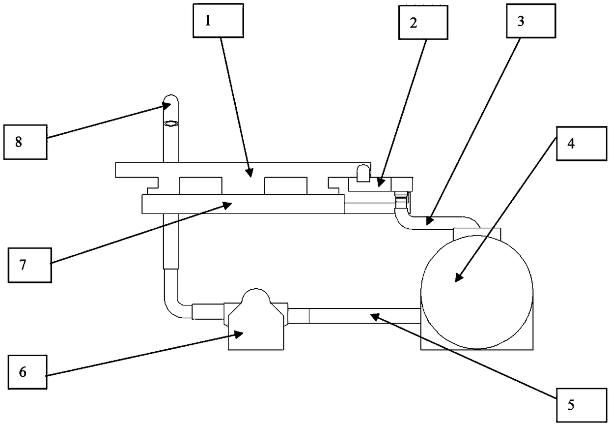
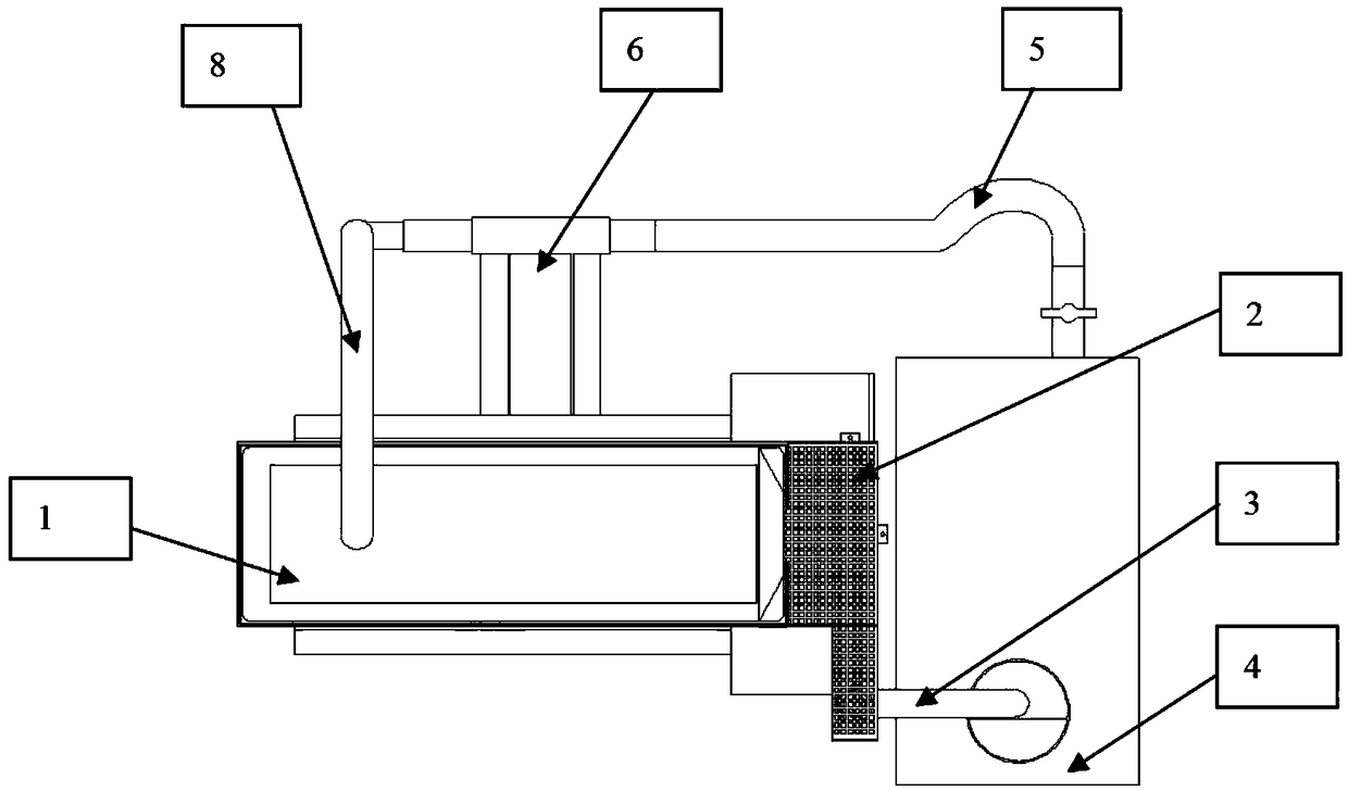
[0018] Such as figure 1 As shown, the circulation system mainly includes a vacuum suction cup 1, a filter tank 2, a water outlet pipe 3, a water tank 4, a cooling water inlet pipe 5, a high-pressure water pump 6, a machining center console 7 and a cooling water outlet pipe 8. Vacuum suction cup 1 is placed on the processing center console 7. After the flatness of the large surface is adjusted to 0.01mm, the vacuum suction cup 1 is fastened on the processing center console 7 with screws, and the filter water tank 2 is connected with the vacuum suction cup 1 through sc...


PUM


Abstract

The invention discloses an external circulation cooling system of a machining center. The external circulation cooling system of the machining center comprises a vacuum chuck, a filtering water tank,a water outlet pipe, a water tank, a cooling water inlet pipe, a high-pressure water pump, a machining center operating table and a cooling water outlet pipe, wherein water tank bodies are arranged onthe periphery of the vacuum chuck. The circulation system can solve the problem that an existing cooling circulation system of a machining center cannot realize circulating cooling of a methyl-polystyrene-type scintillator cooling liquid in a pure water environment.

Description

technical field [0001] The invention belongs to the technical field of industrial processing, in particular to an external circulation cooling system of a processing center. Background technique [0002] Most of the existing machining centers use oily or water-based cutting fluid to cool the parts during the machining process, but for some parts that have strict requirements on the cooling fluid, such as methyl polystyrene scintillators, the machining process The coolant should not be mixed with oily substances, otherwise it will have a great impact on the life of the scintillator. In order to prevent the scintillator from contacting with oil and chemical reagents during the processing, considering that the machine tool transmission system contains oil, and the cutting fluid usually used also contains certain Oily ingredients, so during processing, always ensure that the scintillator is cooled in a pure water environment. [0003] If the traditional cooling circulation syst...

Claims


Application Information

Patent Timeline
Patent Type & Authority Applications(China)
IPC IPC(8): B23Q11/10
CPCB23Q11/10
Inventor 陈绪勇孙克胡可狄陈尧王英杰
Owner BEIJING XINLI MACHINERY
Why Eureka
Eureka Blog
Learn More