Cassegrain reflector array antenna

A reflect array antenna and antenna technology, applied in the microwave field, can solve problems such as working bandwidth limitation, inability to achieve broadband high-gain radiation, etc., and achieve the effects of wide working bandwidth, improved polarization purity, and good performance

Inactive Publication Date: 2019-01-08
AIR FORCE UNIV PLA
View PDF5 Cites 11 Cited by
  • Summary
  • Abstract
  • Description
  • Claims
  • Application Information

AI Technical Summary

Problems solved by technology

The biggest problem with the FP resonant cavity antenna is that its operating bandwidth is doomed to be limited due to the use of a cavity resonant structure, and it is impossible to achieve broadband high-gain radiation.

Method used


Image

  • Cassegrain reflector array antenna
  • Cassegrain reflector array antenna
  • Cassegrain reflector array antenna

Examples


Embodiment Construction

[0019] The technical solution of the present invention will be described in further detail below in conjunction with the accompanying drawings and specific embodiments.

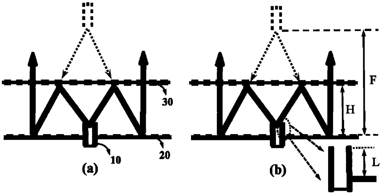
[0020] Such as figure 1 (a), where, figure 1 (a) is the specific composition and working principle diagram of the Cassegrain antenna. The Cassegrain reflector antenna designed in this embodiment consists of three parts, 10 represents the waveguide feed, which can effectively radiate spherical waves in the range of 10-22GHz, 20 represents the main reflector, and 30 represents the Secondary reflector. The working principle of this type of Cassegrain reflectarray antenna is that the y-polarized spherical wave emitted by the waveguide feed 10 is irradiated on the sub-reflector 30 and is totally reflected by it to form a mirror effect, as shown in figure 1 The virtual feed in (a) is shown. After the y-polarized wave reflected by the sub-reflector 30 hits the main reflector 20, the y-polarized spherical wave fr...


PUM

PropertyMeasurementUnit
Thicknessaaaaaaaaaa

Abstract

The invention discloses a Cassegrain reflective array antenna, which comprises a waveguide feed, a main reflective surface and a sub-reflective surface, wherein the waveguide feed, the main reflectivesurface and the height difference between the sub-reflective surfaces are jointly determined by a design focal length and a mirror image principle; the antenna comprises a waveguide feed, a main reflective surface and a sub-reflective surface. The waveguide feed is used for emitting spherical waves; The main reflecting surface is used for converting the spherical wave into plane wave while polarizing and twisting 90 DEG; The sub-reflecting surface has the function of polarization filtering, that is, the sub-reflecting surface can maintain the total transmission of a linearly polarized wave while reflecting the cross-polarized wave. The Cassegrain reflective array antenna realizes 48% of 3dB gain bandwidth and 68.4% of 20dB cross polarization suppression bandwidth, and the profile is almost half of that of the reflective array antenna, thus realizing the characteristics of low profile, wide band, high gain and high polarization purity operation.

Description

technical field [0001] The invention belongs to the field of microwave technology, in particular to a Cassegrain reflection array antenna. Background technique [0002] Electromagnetic metasurfaces have great application prospects in beamforming technology due to their flexible manipulation of electromagnetic wavefronts on two-dimensional surfaces. Especially in the field of high-gain antenna design, high-gain antennas based on electromagnetic metasurface design combine the characteristics of traditional array antennas and parabolic antennas, and have great application prospects in satellite communications, radar detection and other fields. [0003] So far, there are three main techniques of using electromagnetic metasurfaces to realize high-gain antennas: reflective array, transmissive array, and FP resonant cavity antenna. Among them, the reflectarray technology mainly uses the reflective phase modulation unit to design the phase compensation surface, so as to convert the...

Claims


Application Information

Patent Timeline
IPC IPC(8): H01Q19/185H01Q15/24H01Q15/22
CPCH01Q15/22H01Q15/242H01Q19/185
Inventor 郭文龙王光明许河秀蔡通刘凯越
Owner AIR FORCE UNIV PLA
Why Eureka
Try Eureka