A device for all-round direct observation of the shape of small holes in deep penetration welding of metal materials

A technology for deep penetration welding and metal materials, which is applied in the field of devices for all-round direct observation of the shape of small holes in deep penetration welding of metal materials. methods and other issues to achieve high accuracy

Active Publication Date: 2019-07-12
HUNAN UNIV
View PDF2 Cites 0 Cited by
  • Summary
  • Abstract
  • Description
  • Claims
  • Application Information

AI Technical Summary

Problems solved by technology

However, this method has a significant disadvantage: the metal film layer used for welding is a loose structure, which is very different from the actual situation of the dense workpiece used for welding, because the loose multi-layer aluminum film has a deep impact on the laser. The influence of heat transfer, mass transfer and laser energy absorption and transmission process in the fusion welding process is very different from the dense aluminum alloy materials used in engineering practice. The actual situation of the material is very different
[0011] To sum up, in the prior art, there is neither a device and method that can directly observe the shape of the small hole in the deep penetration welding of the metal material, nor a method that can directly observe the shape of the small hole in the deep penetration welding of the metal material. There is no device and method for direct observation of plasma distribution in all directions, and there is also no composite test piece that can be used for direct observation of small holes in deep penetration welding of metal materials.

Method used


Image

  • A device for all-round direct observation of the shape of small holes in deep penetration welding of metal materials
  • A device for all-round direct observation of the shape of small holes in deep penetration welding of metal materials
  • A device for all-round direct observation of the shape of small holes in deep penetration welding of metal materials

Examples


Embodiment 1

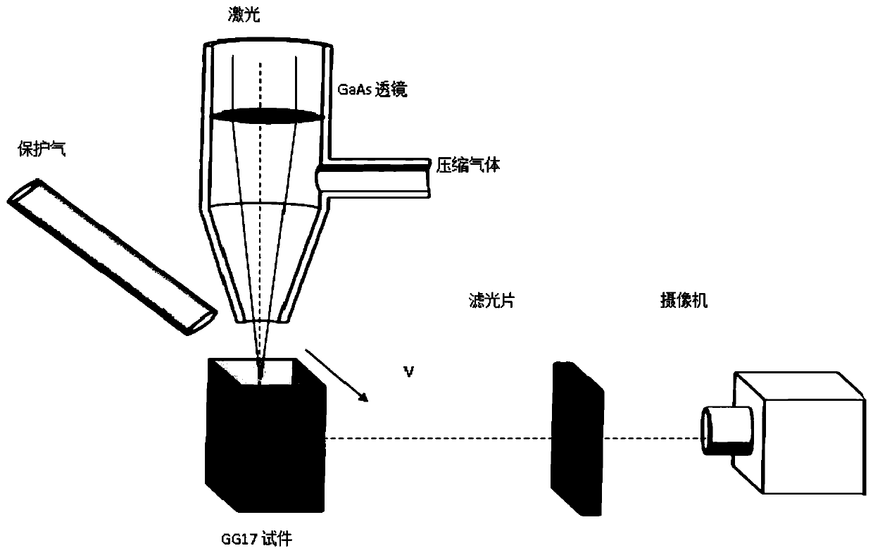
[0062] use as Figure 6 The device shown is a technical solution for directly observing the cross-sectional contour shape of small holes at different depths in layers.

[0063] Such as Figure 6 As shown, a new device for direct observation of small hole morphology in deep penetration welding (laser, electron beam, etc.) of metal materials, including mainly laser beam 1, compressed air inlet 2, laser welding nozzle 3, argon gas nozzle 11 , a laser welding head composed of GaAs focusing lens 12, a composite specimen composed of metal specimen 4 and GG17 specimen 5, and an image capturing component composed of optical filter 6, camera 7 and mirror 8.

[0064] Figure 6 The experimental principle of middle observation: the present invention adopts double-layer composite workpiece, that is, the upper metal test piece 4 is a metal widely used in engineering practice, and the lower part GG17 test piece 5 is transparent, special glass GG17 with good thermal shock resistance, The c...

Embodiment 2

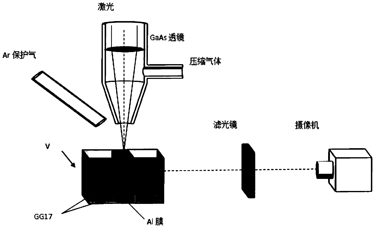
[0069] use as Figure 7 The device shown is a technical solution for directly observing plasma information in the cross-section of small holes at different depths in layers.

[0070] Such as Figure 7 As shown, a new device for direct observation of plasma in small holes for deep penetration welding (laser, electron beam, etc.) of metal materials, including laser beam 1, compressed air inlet 2, laser welding nozzle 3, argon gas nozzle 11. The laser welding head composed of GaAs focusing lens 12, the composite specimen composed of metal specimen 4 and GG17 specimen 5, and the plasma spectrum signal composed of reflector 8, optical fiber fixing plate 13, optical fiber 14 and spectrometer 15 Detect parts.

[0071] Figure 7 Experimental principle of middle observation: the present invention adopts double-layer composite workpiece, that is, the metal test piece 4 of the upper part is a metal widely used in engineering practice, and the GG17 test piece 5 of the lower part is tra...

Embodiment 3

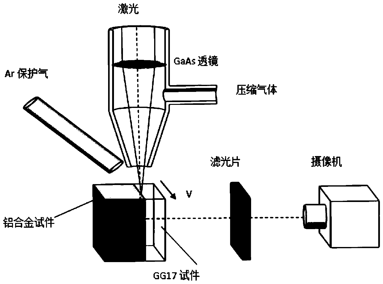
[0074] Figure 8 It is a structural schematic diagram of the composite test piece in the present invention that has formed the small hole 9 in the deep penetration welding process. Before deep penetration welding, the composite test piece described in the present invention does not contain pinholes. The composite test piece includes the metal test piece 4 on the top and the GG17 test piece 5 below, and the top surface of the whole composite test piece, that is, the top surface of the metal test piece, is a plane, and the bottom surface of the metal test piece is the same as the top surface of the GG17 test piece. The surfaces are all smooth joint surfaces, and the joint surface (88) of the metal test piece and the GG17 test piece and the top surface of the composite test piece form an angle of n degrees, and 0°

[0075] When preparing the composite test piece of the present invention (its structure sees for example Figure 8 ) process, the joint surfaces of the metal ...


PUM


Abstract

The invention provides a metal material penetration fusion welding small hole morphology all-dimensional direct observation device. The device comprises a welding head, a composite test piece locatedbelow the welding head and an image capturing component for observing small hole morphology; the welding head is a welding head capable of using lasers or electron beams; the composite test piece includes a metal test piece on the upper portion and a GG17 test piece on the lower portion, the top surface of the entire composite test piece, that is, the top surface of the metal test piece is a plane, the bottom surface of the metal test piece and the top surface of the GG17 test piece are both smooth joint faces, and an n-degree angle is formed between the joint faces of the metal test piece andthe GG17 test piece and the top surface of the composite test piece, and n is larger than 0 and smaller than 90 degrees; and the image capturing component includes a video camera. The device can be used for metal material penetration fusion welding small hole morphology all-dimensional direct observation, no observation dead angle exists, and more accurate small hole shapes can be provided for study of small hole behaviors and an energy absorption mechanism in small holes.

Description

technical field [0001] The invention relates to the field of deep penetration welding, in particular to a device for directly observing the morphology of small holes in deep penetration welding of metal materials in all directions. Background technique [0002] As a high-quality and efficient welding method, deep penetration welding (including laser, electron beam, etc.) has the advantages of fast welding speed, large weld depth-to-width ratio, small heat-affected zone and welding deformation, and is widely used in steel, nuclear power, aerospace, etc. It has been more and more widely used in major military and civil projects such as railway transportation, automobile, electronic industry, etc., especially in the lightweight of transportation vehicles (welding of thin-walled components and lightweight materials such as aluminum and magnesium alloys). play an increasingly important role. [0003] (1) Current status of small hole observation technology [0004] The essential...

Claims


Application Information

Patent Timeline
Patent Type & Authority Patents(China)
IPC IPC(8): B23K37/00B23K31/00
CPCB23K31/00B23K37/00
Inventor 金湘中蒋志伟周昕宇
Owner HUNAN UNIV
Why Eureka
Try Eureka