
Neodymium iron boron magnet chamfering device

A chamfering device, NdFeB technology, applied in the direction of grinding/polishing safety devices, grinding machines, grinding machine parts, etc., can solve the problems of low chamfering efficiency, high defective rate, complex structure, etc., to achieve convenient Feeding and discharging, automatic uniform feeding, and the effect of improving the quality of chamfering

Active Publication Date: 2019-01-11
京磁材料科技股份有限公司
View PDF7 Cites 3 Cited by
  • Summary
  • Abstract
  • Description
  • Claims
  • Application Information

AI Technical Summary

Problems solved by technology

[0002] At present, the chamfering of square NdFeB workpieces is mostly done by manual chamfering, the chamfering efficiency is low, and the manual chamfering is greatly affected by human subjective factors, and the chamfering quality is unstable
Although the existing chamfering equipment solves the problem of unstable chamfering quality, most of them chamfer the two long opposite sides of the workpiece step by step, and the chamfering efficiency is still low. In addition, during the chamfering process, the workpiece The movement is driven by the cam to feed the material. The processing equipment is bulky and complex in structure, or the workpiece is moved by the paddle, so that the latter workpiece hits the previous workpiece to drive the workpiece forward. Although it reduces the size of the equipment and improves the Chamfering efficiency, but it is not easy to discharge after chamfering, and the defective rate is high

Method used


Image

  • Neodymium iron boron magnet chamfering device
  • Neodymium iron boron magnet chamfering device
  • Neodymium iron boron magnet chamfering device

Examples


Embodiment Construction

[0024] The present invention will be described in further detail below in conjunction with the embodiments and accompanying drawings, so that those skilled in the art can implement it with reference to the description.

[0025] It should be noted that the experimental methods described in the following embodiments, unless otherwise specified, are conventional methods, and the reagents and materials, if not otherwise specified, can be obtained from commercial sources; in the description of the present invention, The terms "landscape", "portrait", "top", "bottom", "front", "rear", "left", "right", "vertical", "horizontal", "top", "bottom", The orientation or positional relationship indicated by "inner", "outer", etc. is based on the orientation or positional relationship shown in the drawings, which is only for the convenience of describing the present invention and simplifying the description, and does not indicate or imply that the referred device or element must have Certain ...


PUM


Abstract

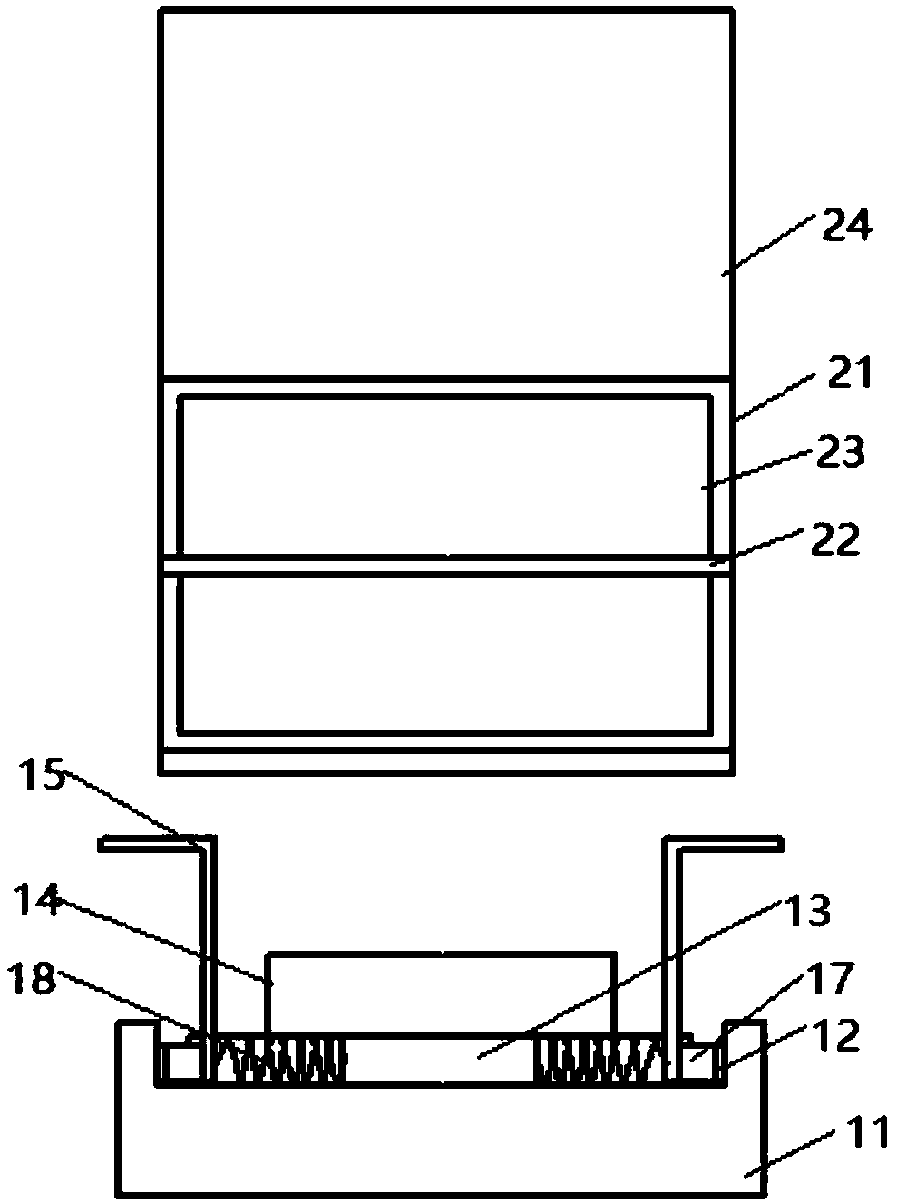
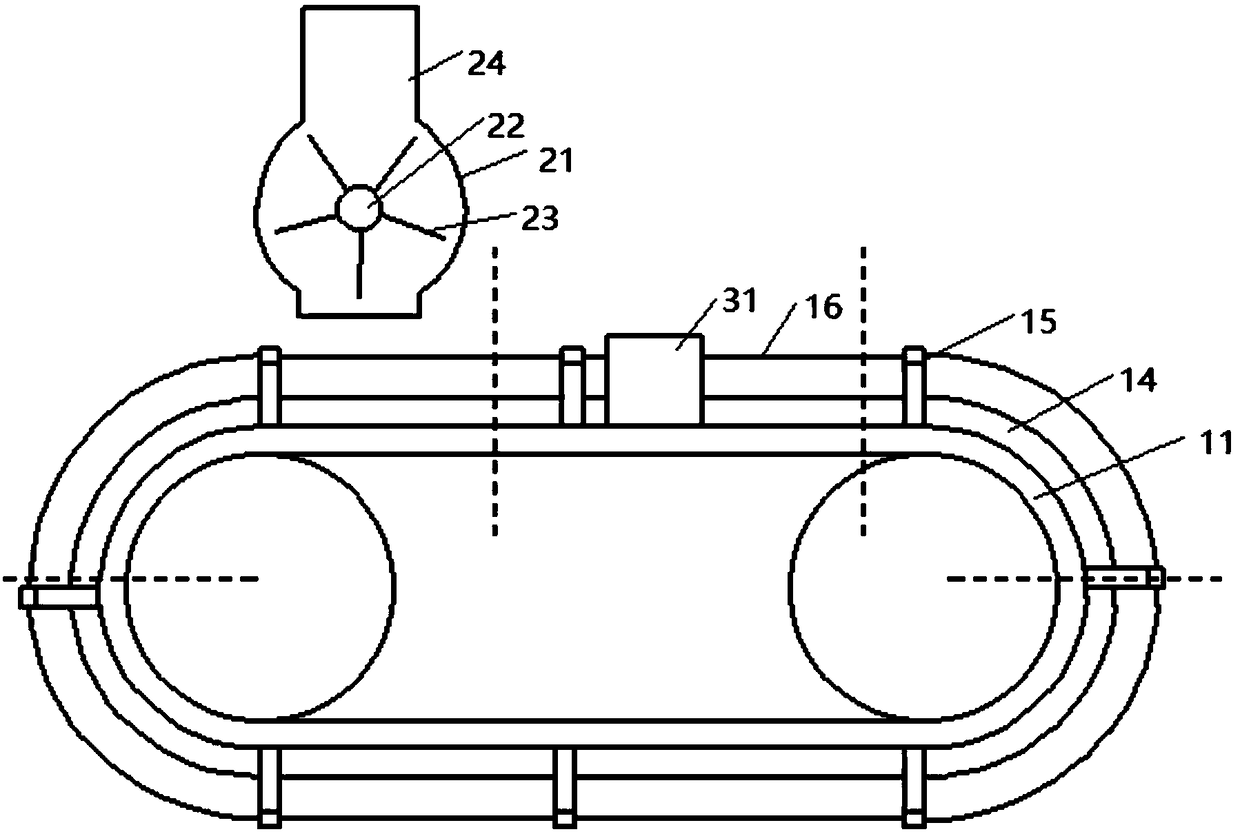
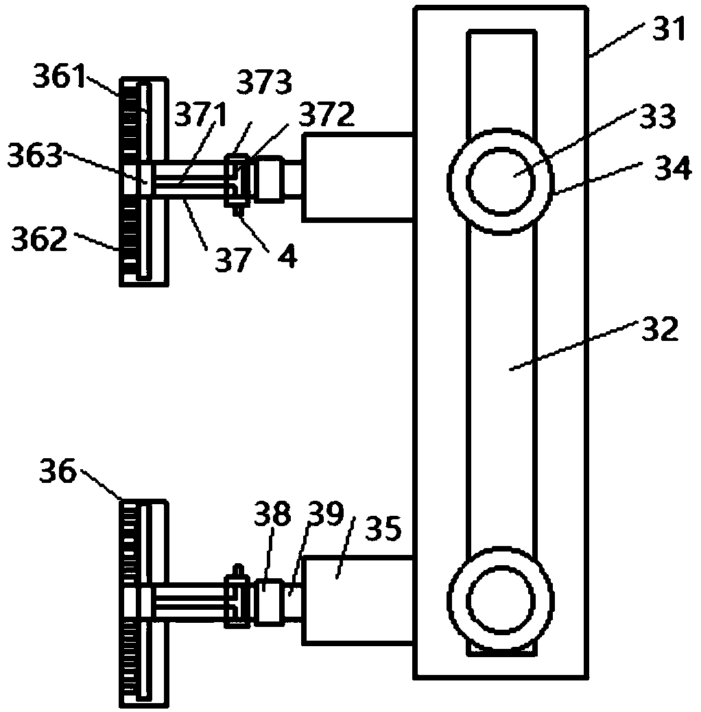
The invention discloses a neodymium iron boron magnet chamfering device which comprises a ribbon conveyer. A feeding area, a chamfering area and an unloading area are successively arranged from left to right on a rack on the upper part. Electromagnets are separately arranged on two sides of the racks of the feeding area and the unloading area. Pairs of blind slots are formed in a spaced manner along the length direction of a belt of the ribbon conveyor, and the any pair of blind slots is symmetrically formed along the width direction of the belt; the device also comprises a bump and pairs of adjusting rods, any pair of adjusting rods comprises two integrally formed L-shaped rods, the horizontal rods are above, the free ends of the horizontal rods are arranged outward, an elastic plate strip is connected between the free ends of two adjacent horizontal rods, vertical rods are arranged downward, and permanent magnets attractive to the electromagnets magnetically are arranged on the outersides of the free ends of the vertical rods. The device also comprises pairs of springs, any spring is arranged in each blind slot, one end of the spring is connected to the inner end surface of eachblind slot, and the other end is connected to the inner side of the free end of each vertical rod. The neodymium iron boron magnet chamfering device has the advantages of being convenient to feed anddischarge, good in chamfering quality, high in work efficiency and the like.

Description

technical field [0001] The invention relates to the field of NdFeB chamfering. More specifically, the present invention relates to an NdFeB magnet chamfering device. Background technique [0002] At present, the chamfering of square NdFeB workpieces is mostly done by manual chamfering, the chamfering efficiency is low, and the manual chamfering is greatly affected by human subjective factors, and the chamfering quality is unstable. Although the existing chamfering equipment solves the problem of unstable chamfering quality, most of them chamfer the two long opposite sides of the workpiece step by step, and the chamfering efficiency is still low. In addition, during the chamfering process, the workpiece The movement is driven by the cam to feed the material. The processing equipment is bulky and complex in structure, or the workpiece is moved by the paddle, so that the latter workpiece hits the previous workpiece to drive the workpiece forward. Although it reduces the size o...

Claims


Application Information

Patent Timeline
Patent Type & Authority Applications(China)
IPC IPC(8): B24B9/02B24B41/00B24B41/02B24B41/06B24B55/02
CPCB24B9/02B24B41/005B24B41/02B24B41/06B24B55/02
Inventor 房宏伟
Owner 京磁材料科技股份有限公司
Learn More