Bionic design method making centrifugal pump have resistance reducing and noise lowering performance

A design method and technology of centrifugal pumps, which are applied to components, pumps, and calculations of pumping devices for elastic fluids, can solve problems such as time-consuming, energy-intensive and labor costs, no design solutions are provided, and the process is cumbersome and complicated, etc., to achieve Simple design formula, good pressure pulsation, easy and accurate results

Active Publication Date: 2019-01-11
JIANGSU UNIV
View PDF8 Cites 9 Cited by
  • Summary
  • Abstract
  • Description
  • Claims
  • Application Information

AI Technical Summary

Problems solved by technology

This design method can design high-performance, low-noise centrifugal pump blades, but the process is cumbersome and complicated, and requires a lot of time, energy and labor costs.
Patent No. 201510351784.7 discloses a vibration-reducing and noise-reducing centrifugal pump with a bionic structure, which adds many prism structures to the tongue and impeller, and makes innovations in the volute structure, but its bionic structure The design is relatively broad, it only gives a certain range of values, there is no specific formula to guide the design parameters, and it does not provide a complete and accurate design plan, and the design method given is very general and untargeted. Many special centrifugal pump products may be difficult to achieve on

Method used


Image

  • Bionic design method making centrifugal pump have resistance reducing and noise lowering performance
  • Bionic design method making centrifugal pump have resistance reducing and noise lowering performance
  • Bionic design method making centrifugal pump have resistance reducing and noise lowering performance

Examples


Embodiment Construction

[0054] The present invention will be further described below in conjunction with the accompanying drawings and specific embodiments, but the protection scope of the present invention is not limited thereto.

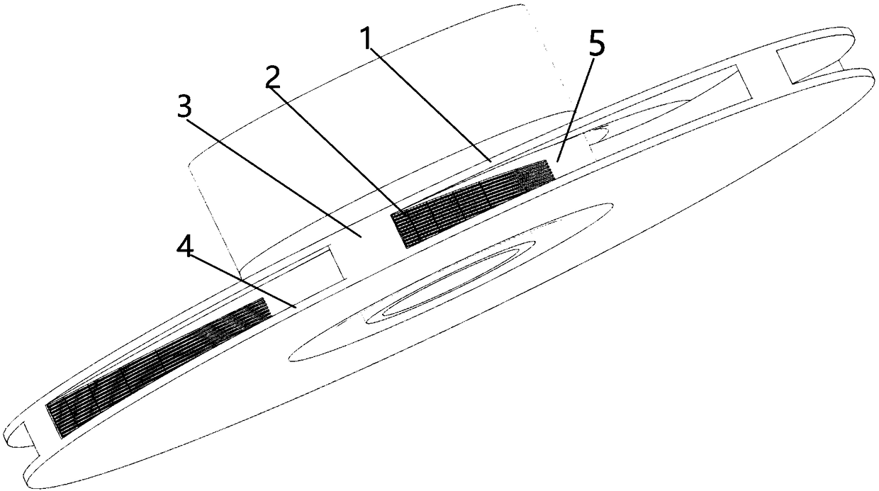
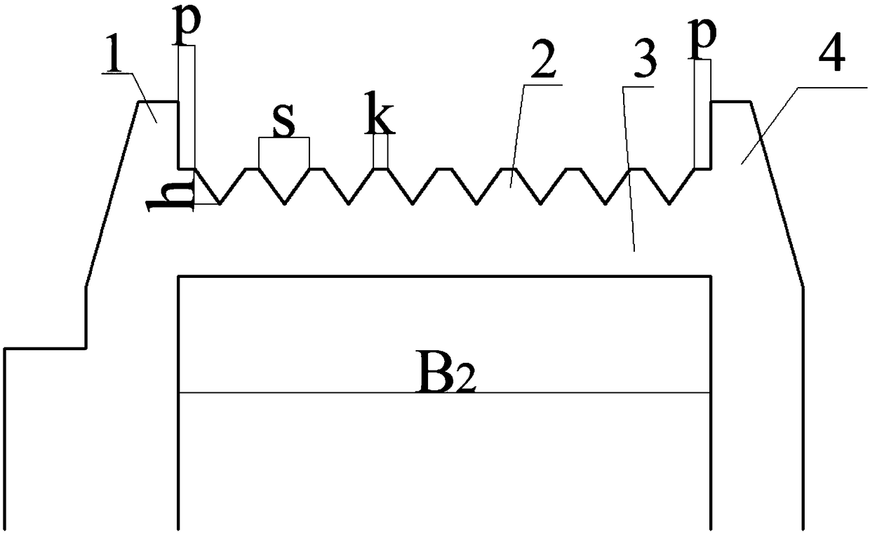
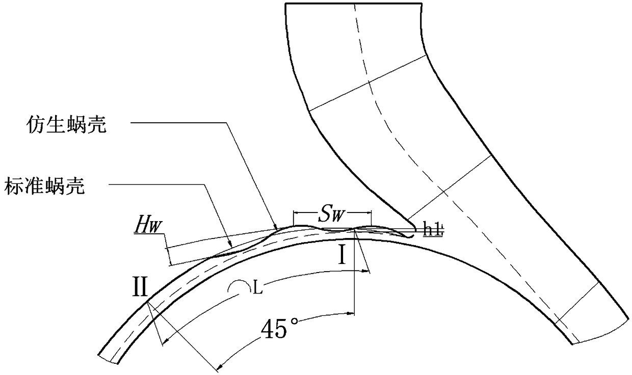
[0055] Such as figure 1 As shown, in this embodiment, a closed structure smooth centrifugal pump is used for bionic design. The smooth centrifugal pump mainly includes an impeller and a volute. The specific parameters of the smooth centrifugal pump are: flow rate Q=25m3 / h=0.006944m 3 / s, head H=10m, speed n=1450r / min, specific speed n s =78.4, the diameter D of the impeller outlet 3 of the model pump 2 is 0.2m, the width B of the impeller outlet 3 2 is 0.008m, the arc length L of the cross-section curve between the first and second sections of the standard volute outer profile is 0.31m, and the height between the outer contour curve and the base circle at the first section of the volute is h 1 0.01m, Section I is the cross section where the centerline of the outlet of...


PUM


Abstract

The invention provides a bionic design method making a centrifugal pump have resistance reducing and noise lowering performance. The position, close to a blade outlet, of a blade work face of an impeller is provided with a plurality of V-shaped grooves similar with shark skin; the plurality of V-shaped grooves are parallel with each other and are arranged in the hydraulic force flow direction; thecut-off surface, at the position of the blade outlet, of each V-shaped groove is flush with the blade outlet; an arc line protruding structure similar with the front edge of a bird wing is arranged nearby a separation tongue of a volute; the contour of the longitudinal section of the arc line protruding structure is in the shape of a linear sine curve; a starting point of the arc line protrudingstructure is located at the position, tangent with the basic circle, of the separation tongue; and an ending point is located between a first fracture surface and a second fracture surface of the volute. Due to the structural design of the V-shaped grooves of the bionic design method, the jet wake and boundary layer separation phenomenon can be effectively controlled, the impeller working resistance is lowered, the work efficiency of the centrifugal pump is improved, the arc line protruding structure can effectively control the pressure pulse of the centrifugal pump at the position of the separation tongue, the dynamic and static interference effect at the position is reduced, and therefore noise generated when the centrifugal pump runs is lowered.

Description

technical field [0001] The invention relates to the field of fluid machinery, in particular to a bionic design method for making a centrifugal pump have the performance of reducing drag and noise. Background technique [0002] As important energy conversion equipment and fluid delivery devices, pumps are widely used in various sectors of the national economy and cutting-edge technical fields such as submarines, ships, and aerospace, of which about 70% are centrifugal pumps. Centrifugal pumps are one of the main conveying equipment, and the requirements for efficient and stable work are gradually increasing. In the process of fluid delivery and energy conversion, the pump is inevitably accompanied by hydraulic loss caused by impact, shedding and mechanical loss, resulting in flow instability and energy waste. At the same time, due to the complex internal flow structure, the centrifugal pump operation process Often accompanied by strong noise. [0003] Since the water pump i...

Claims


Application Information

Patent Timeline
Patent Type & Authority Applications(China)
IPC IPC(8): F04D29/24F04D29/42F04D29/66G06F17/50
CPCF04D29/245F04D29/426F04D29/669G06F30/17Y02T90/00
Inventor 戈志鹏董亮刘骏旻代翠王勇
Owner JIANGSU UNIV
Why Eureka
Try Eureka