
Measuring method for ellipsometry of attosecond pulse

An ellipsometry and pulse technology, applied in the field of ultrafast laser measurement, can solve the problems of weak attosecond pulse intensity, complex operation accuracy, and extremely high requirements, achieve simple and accurate measurement methods, simplify measurement methods, and avoid experimental devices and operations. Effect

Inactive Publication Date: 2019-01-11
HUAZHONG UNIV OF SCI & TECH
View PDF4 Cites 6 Cited by
  • Summary
  • Abstract
  • Description
  • Claims
  • Application Information

AI Technical Summary

Problems solved by technology

However, the pulsed beams in the ultraviolet and extreme ultraviolet bands are absorbed by the medium when propagating in the optical element, so the ellipsometric properties of the attosecond pulse cannot be measured using the transmission optical element
Recently, some researchers have proposed to use reflective polarization-dependent optical components (such as gold-plated mirrors, etc.) Extremely high; the second requirement is that the attosecond light intensity after reflection can be measured, but the attosecond pulse intensity obtained experimentally is very weak, and the reflectivity of optical components such as gold-plated mirrors is limited, so this scheme is difficult to measure accurately. Elliptic properties of second pulses
Another scheme proposed by the researchers is to add a weak near-infrared laser pulse to the attosecond pulse. By scanning the time delay between the attosecond pulse and the near-infrared laser pulse, the single-photon ring generated from the attosecond pulse excited medium Attosecond pulse ellipsometric characteristics are extracted from the asymmetry, but there are two major problems in this scheme: one is that the attosecond pulse intensity is required to be high enough to excite the medium to produce a single photon ring; the other is that the attosecond pulse and the Time delay of near-infrared laser pulses and recording the signal at each time delay
Therefore, so far, there is no simple and convenient method to directly and accurately measure the ellipsometric properties of attosecond pulses

Method used

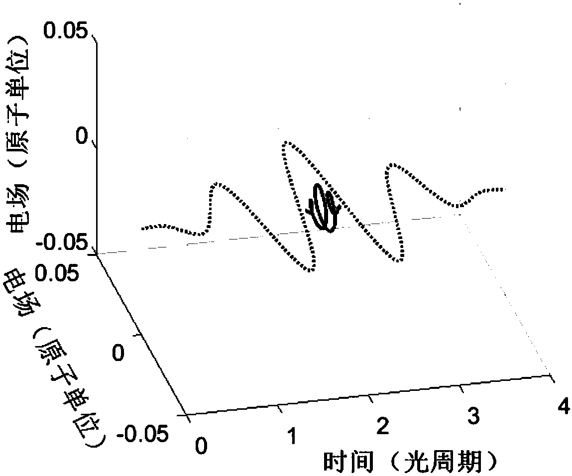
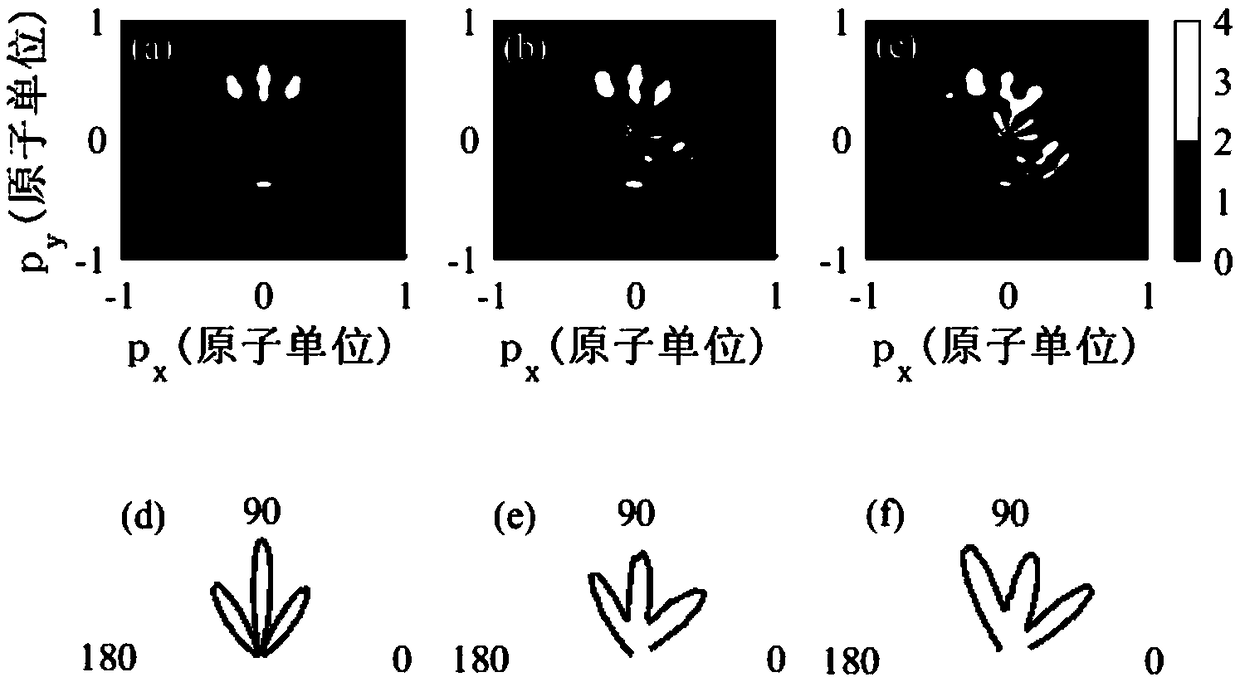
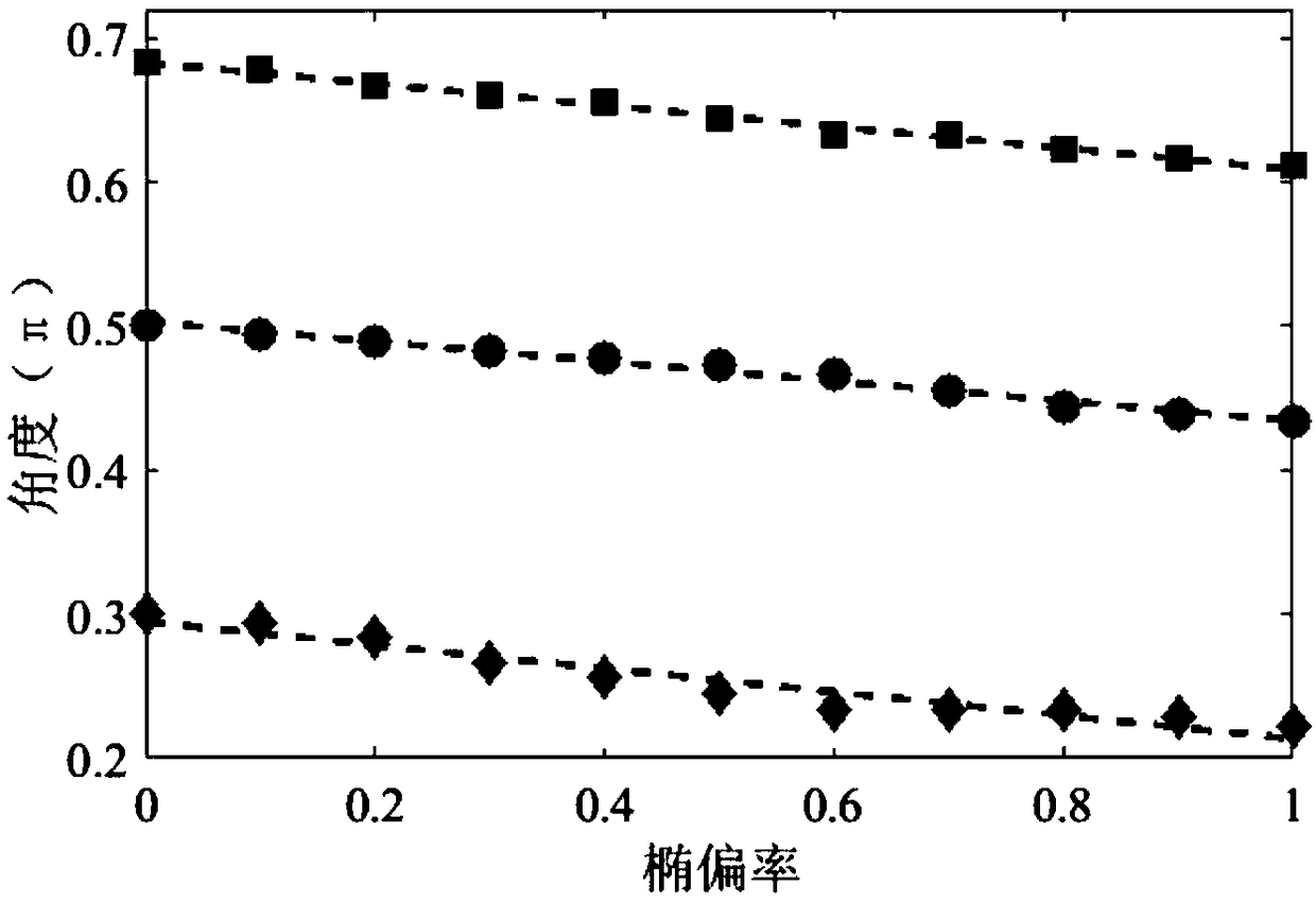

Image

  • Measuring method for ellipsometry of attosecond pulse
  • Measuring method for ellipsometry of attosecond pulse
  • Measuring method for ellipsometry of attosecond pulse

Examples


Embodiment Construction

[0015] Specific implementation examples

[0016] In order to make the object, technical solution and advantages of the present invention clearer, the present invention will be further described in detail below in conjunction with the accompanying drawings and embodiments. It should be understood that the specific embodiments described here are only used to explain the present invention, not to limit the present invention.

[0017] The invention provides a method for calibrating the attosecond pulse ellipticity only by measuring the photoelectron spectrum and analyzing the angle distribution of the photoelectron spectrum. The method is characterized in that, firstly, the attosecond pulse whose ellipticity is to be measured is combined with a linearly polarized near-infrared laser pulse, the ionized atoms generate photoelectron signals, and the photoelectron signals are collected to obtain the photoelectron spectrum; secondly, the time-dependent Schrödinger equation Calculate...


PUM


Abstract

The invention discloses a measuring method for ellipsometry of an attosecond pulse using a photoelectron spectrum. The method comprises the steps of: first, focusing a combined beam of a near-infraredlaser pulse and an attosecond pulse on a gaseous medium, forming a photoelectron signal containing attosecond pulse information by ionization, and collecting the photoelectron signal to obtain a photoelectron spectrum; then, calculating the relationship between the photoelectron spectrum and the attosecond pulse using the time-dependent Schr dinger equation, and obtaining the ellipsometry of theattosecond pulse by analyzing the photoelectron spectrum. The invention provides a method for obtaining the ellipsometry of the attosecond pulse by detecting the photoelectron spectrum, which is a simple and effective method with a wide range of applicability.

Description

technical field [0001] The invention relates to the technical field of ultrafast laser measurement, in particular to a method for measuring attosecond pulse ellipticity. Background technique [0002] In recent years, with the development of strong field physics, people have made important breakthroughs in the field of attosecond science. Especially isolated attosecond pulses generated by high-order harmonic technology, the isolated attosecond pulse with the shortest pulse width has reached 43 attosecond [T.Gaumnitz et al, Streaking of 43-attosecond soft-X-ray pulses generated by apassively CEP-stable mid-infrared driver, Optics Express 25, 27506-27518(2017)], can achieve very good time resolution, for probing the internal structure of atoms, molecules and solid matter and real-time detection and control of ultrafast electron dynamics process Powerful tools are provided. For example, isolated attosecond pulses have great advantages in the detection of molecular circular dic...

Claims


Application Information

Patent Timeline
IPC IPC(8): G01J4/00G01J11/00
CPCG01J4/00G01J11/00
Inventor 兰鹏飞翟春洋张银福何立新陆培祥
Owner HUAZHONG UNIV OF SCI & TECH
Learn More