Exhaust gas treatment device and exhaust gas treatment method for exhaust gas from magnet sintering

A waste gas treatment device and waste gas technology, which are applied in the field of waste gas treatment devices and waste gas treatment devices, can solve the problems of poor purification effect of waste gas devices, and achieve the effects of saving resources, convenient use and prolonging service life.

Active Publication Date: 2020-10-13
安徽万磁电子股份有限公司
View PDF5 Cites 0 Cited by
  • Summary
  • Abstract
  • Description
  • Claims
  • Application Information

AI Technical Summary

Problems solved by technology

[0005] Aiming at the deficiencies of the prior art, the present invention provides a waste gas treatment device for waste gas from magnet sintering, which has the advantages of high heat recovery rate and good purification effect, and solves the problem of poor purification effect of the existing waste gas device

Method used


Image

  • Exhaust gas treatment device and exhaust gas treatment method for exhaust gas from magnet sintering
  • Exhaust gas treatment device and exhaust gas treatment method for exhaust gas from magnet sintering
  • Exhaust gas treatment device and exhaust gas treatment method for exhaust gas from magnet sintering

Examples


Embodiment 1

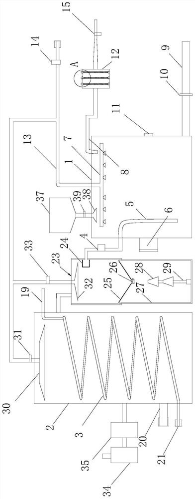
[0066] see figure 1 , The waste gas treatment device for waste gas from magnet sintering in this embodiment includes a spray bin 1 , a drug delivery mechanism, a heat recovery mechanism, a dust removal mechanism, an exhaust gas purification mechanism, an air inlet valve 4 , a water inlet valve 14 , and a controller 6 .

[0067] The spray chamber 1 is used to spray and purify the exhaust gas. An atomizing nozzle 7 for spraying is set in the spray chamber 1 of the waste gas by using water, and the spray chamber 1 is connected to a spray chamber 1 for discharge. The drainpipe 9 for accumulated water, the top of the spray chamber 1 is also connected to one end of an exhaust pipe 8, after the waste gas flows into the spray chamber 1, the atomizing nozzle 7 sprays the raw water, and the spray chamber 1 The waste gas is purified, and the raw water forms waste water after dissolving the soluble harmful substances in the waste gas. The waste water flows out from the drain pipe 9, and t...

Embodiment 2

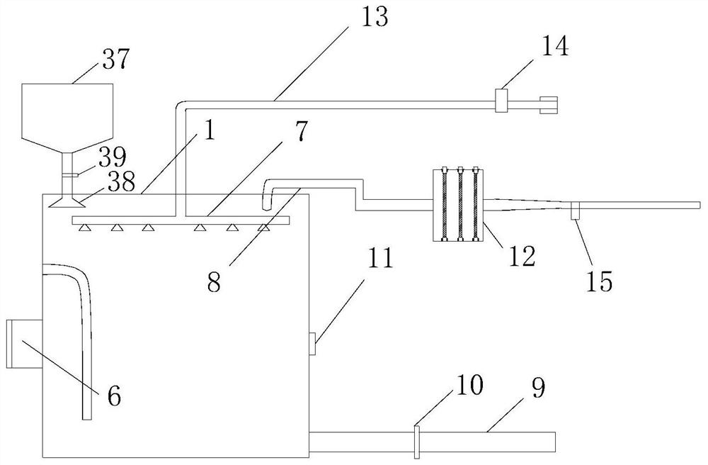
[0088] see image 3The difference between the exhaust gas treatment device of this embodiment and the exhaust gas treatment device of Embodiment 1 is that the exhaust gas treatment device of this embodiment has two exhaust gas purification bins 12, and one side of the two exhaust gas purification bins 12 is respectively connected by an outlet valve 16. Exhaust pipe 8 has also increased water outlet valve 10 and water level detector 11 in addition.

[0089] The water outlet valve 10 is arranged on the drain pipe 9 and is used for opening and closing the drain pipe 9 .

[0090] The water level detector 11 is arranged in the spray chamber 1 and is used for detecting the water level value of the accumulated water in the spray chamber 1 .

[0091] According to the water level value detected by the water level detector 11, the controller 6 controls the water outlet valve 10 to open when the water level value is not less than a preset high water level value; otherwise, the controlle...


PUM


Abstract

The invention discloses a waste gas treatment device and a waste gas treatment method for waste gas from magnet sintering. Valves, controllers, atomizing nozzles for spraying are installed in the spray chamber, the heat recovery mechanism includes a heat recovery chamber for circulating exhaust gas and cooling pipes for circulating cooling liquid, and a dust collection chamber for the exhaust gas. The dust is filtered and collected by classification, the exhaust gas purification mechanism is connected with a gas detection device, the intake valve is used to adjust the flow of waste gas flowing from the heat recovery chamber to the spray chamber, and the water inlet valve is used to adjust the water spray volume of the atomizing nozzle. The present invention detects the concentration of pollutants in the purified gas through a gas detection device. When the concentration of pollutants is not less than a preset concentration, the controller controls the flow rate of the exhaust gas to decrease and the water spray volume of the atomizing nozzle to increase, thereby improving the purification of the exhaust gas. As a result, water resources are also used rationally.

Description

technical field [0001] The invention relates to a waste gas treatment device in the technical field of waste gas treatment, in particular to a waste gas treatment device for magnet sintering waste gas and a waste gas treatment method thereof. Background technique [0002] The composition of magnets includes atoms such as iron, cobalt, and nickel. The internal structure of the atoms is relatively special, and the magnet itself has a magnetic moment. A magnet can generate a magnetic field and has the property of attracting ferromagnetic substances such as iron, nickel, cobalt and other metals. After thousands of years of development, magnets have become powerful materials in people's lives and are widely used in various fields. Therefore, it is of great significance to improve the quality of magnets. [0003] Existing magnet production factories need to sinter raw materials when producing magnets, and magnet sintering furnaces will generate a large amount of high-heat exhaus...

Claims


Application Information

Patent Timeline
Patent Type & Authority Patents(China)
IPC IPC(8): B01D53/75B01D53/78B01D53/48B01D53/04B01D53/02B01D50/00F27D17/00
CPCB01D53/02B01D53/04B01D53/346B01D53/48B01D53/75B01D53/78F27D17/004F27D17/008B01D50/60Y02P10/25
Inventor 唐睿何进陈益民
Owner 安徽万磁电子股份有限公司
Why Eureka
Try Eureka