
Hollow spindle device for powder concentrator

A hollow main shaft and main shaft device technology, applied in the directions of shafts, couplings, shafts and bearings, can solve the problems of inconvenient main shaft transportation, installation and maintenance, adverse effects of powder separator equipment, and easy swinging of main shaft cage wheels. Achieve the effect of increasing disassembly performance, reducing machining workload, and reducing steel investment

Pending Publication Date: 2019-01-15
曾鲁庆
View PDF3 Cites 0 Cited by
  • Summary
  • Abstract
  • Description
  • Claims
  • Application Information

AI Technical Summary

Problems solved by technology

The main shaft of the traditional powder classifier is usually a solid main shaft. The defect of this design is: because the main shaft is an important force-bearing part, it is affected by the torque transmitted by the drive motor of the powder classifier through the reducer. In order to prevent the main shaft from torsion damage failure, The main shaft is generally made of high-quality alloy steel, and the shaft diameter is generally set larger so that the main shaft can obtain a larger torsional section coefficient, which will easily cause a large investment in high-quality steel and difficulties in processing and manufacturing.
The main shaft of the traditional powder classifier usually sets the main shaft and the cage wheel as a whole, which is not convenient for the transportation, installation and maintenance of the main shaft and the cage wheel.
The main shaft of the traditional powder classifier usually sets the upper and lower bearings of the main shaft on the upper end of the main shaft. During operation, the lower part of the main shaft and the cage wheel are prone to swing, which will adversely affect the upper and lower bearings and the entire powder classifier equipment.

Method used


Image

  • Hollow spindle device for powder concentrator
  • Hollow spindle device for powder concentrator

Examples


Embodiment Construction

[0018] Below in conjunction with specific embodiment and accompanying drawing, the utility model is further described.

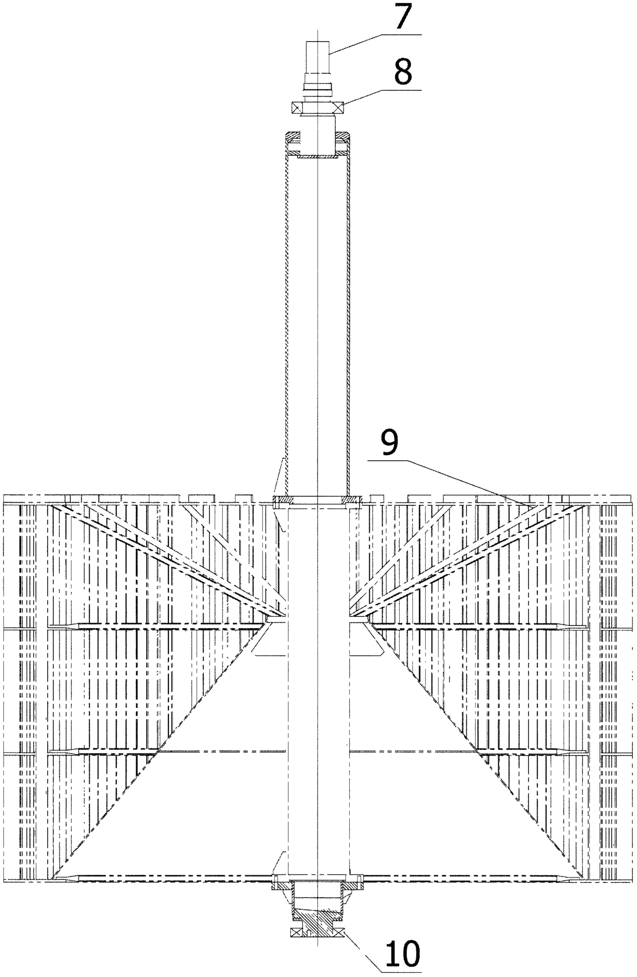
[0019] Such as Figures 1 to 2 As shown, a hollow spindle device used in a powder classifier, including shaft (1) 1, shaft (2) 6, seamless steel pipe for structure (1) 2, seamless steel pipe for structure (2) 4, flange (1) 3, flange (2) 5, the main part of the main shaft is a hollow structure, the shaft (1) 1, flange (1) 3 are fixed on the structural seamless steel pipe (1) 2 by welding, forming the main shaft the upper part of the . Axle (two) 6 and flange (two) 5 are fixed on the structural seamless steel pipe (two) 4 by welding, forming the lower half of the main shaft. The cage wheel is installed between the upper half and the lower half of the main shaft, and the cage wheel is fixed by the connecting bolts of flange (1) 3, flange (2) 5 and the matching flange on the cage wheel, thus forming a complete set of spindle device.

[0020] Work process of ...


PUM


Abstract

The invention discloses a hollow spindle device for a powder concentrator and relates to a spindle device for the powder concentrator. The spindle device comprises a shaft I, a shaft II, a structuralseamless steel pipe I, a structural seamless steel pipe II, a flange I and a flange II, and is characterized in that the main portion ofa spindle is of a hollow structure; the shaft I and the flange Iare fixed to the structural seamless steel pipe I in a welded mode to form the upper half portion of the spindle; the shaft II and the flange II are fixed to the structural seamless steel pipe II ina welded mode to form a lower half portion of the spindle; a cage wheel is mounted between the upper half portion and the lower half portion of the spindle; the cage wheel is fixed through the flangeI, the flange II and flange connecting bolts matched with the cage wheel to form thecomplete set of spindle device. The hollow spindle device is the novel spindle device with the higher torsion property on the premise of not increasing steel input.

Description

technical field [0001] The invention relates to a main shaft device for a powder separator, which is suitable for powder separators of grinding systems in industries such as building materials, chemical industry, metallurgy, power plants, and mines. Background technique [0002] The powder separator is one of the important grinding system equipment. The material enters the powder separator from the chute, and the material is guided into the grinding unit by the chute. After the material is finely ground, it enters the powder separator along with the direction of the internal air flow. Separation occurs under the dual action of blades and rotating cage wheels. The fine powder continues to rise and flows out from the air outlet of the powder classifier, and is collected by the powder classifier and bag dust collector. Coarse powder settles under the centrifugal force of the cage wheel and its own gravity, and enters the grinding unit through the ash hopper of the classifier f...

Claims


Application Information

Patent Timeline
Patent Type & Authority Applications(China)
IPC IPC(8): B02C23/32B07B11/00F16C3/02F16D1/076
CPCF16C3/023F16D1/076B02C23/32B07B11/00
Inventor 曾鲁庆
Owner 曾鲁庆
Learn More