Slotting device for producing antistatic aramid composite floor and method of using slotting device

A composite floor and anti-static technology, which is applied in the direction of slotting machines, mortising machines, wood processing appliances, etc., can solve the problems of not being able to slot the end face of the bottom plate, and the control of the slotting depth is inaccurate, so as to achieve simple structure and easy installation. Easy to fix and slotting effect

Inactive Publication Date: 2019-01-15
鑫材泰克(天津)复合材料有限公司
View PDF1 Cites 4 Cited by
  • Summary
  • Abstract
  • Description
  • Claims
  • Application Information

AI Technical Summary

Problems solved by technology

[0004] The slotting machine of the above-mentioned patent cannot slot the end face of the bottom plate when used, and the slotting depth control is inaccurate

Method used


Image

  • Slotting device for producing antistatic aramid composite floor and method of using slotting device
  • Slotting device for producing antistatic aramid composite floor and method of using slotting device
  • Slotting device for producing antistatic aramid composite floor and method of using slotting device

Examples


Embodiment 1

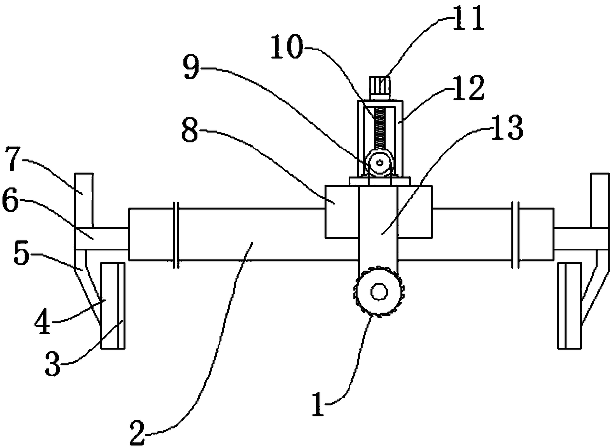
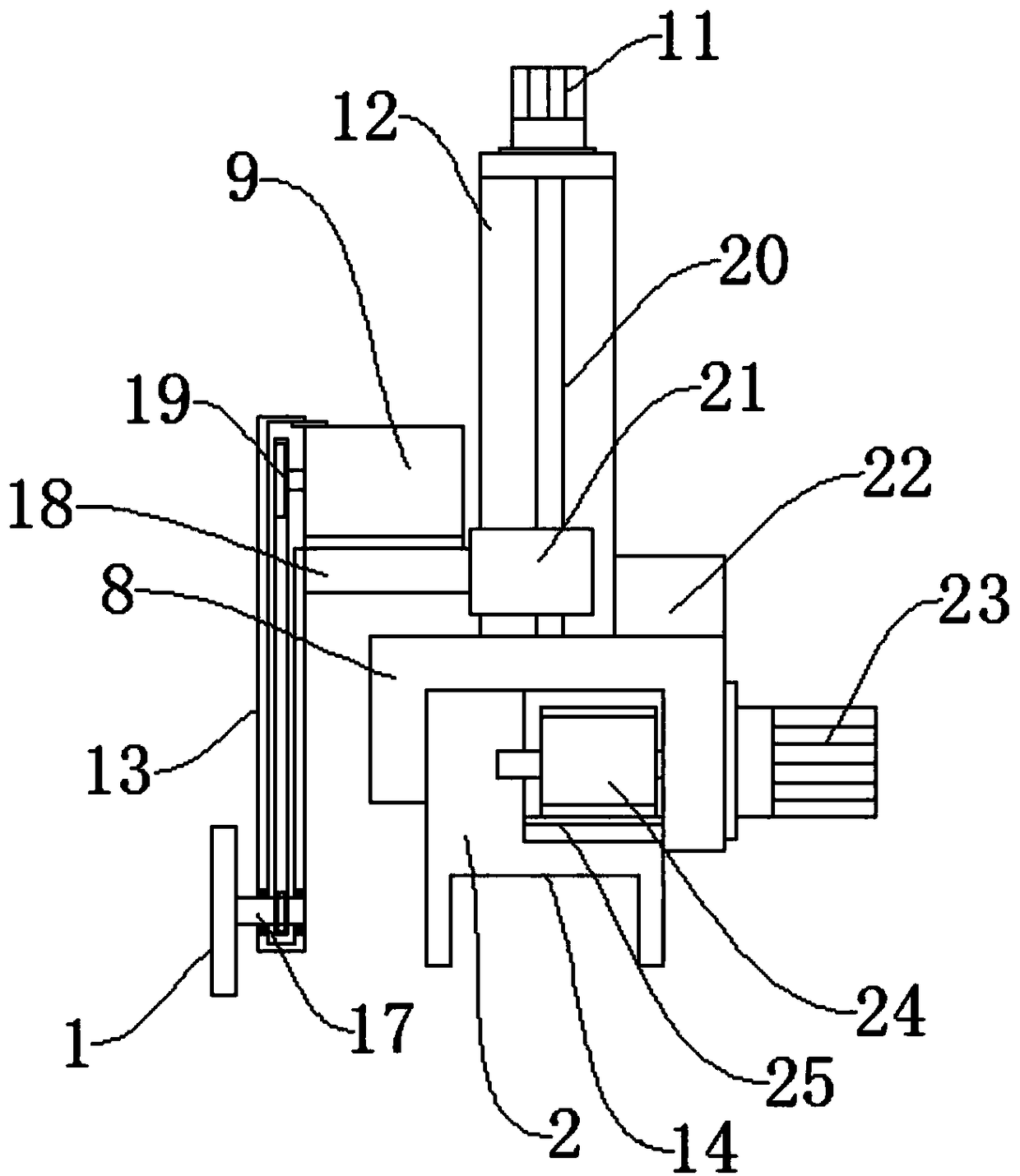
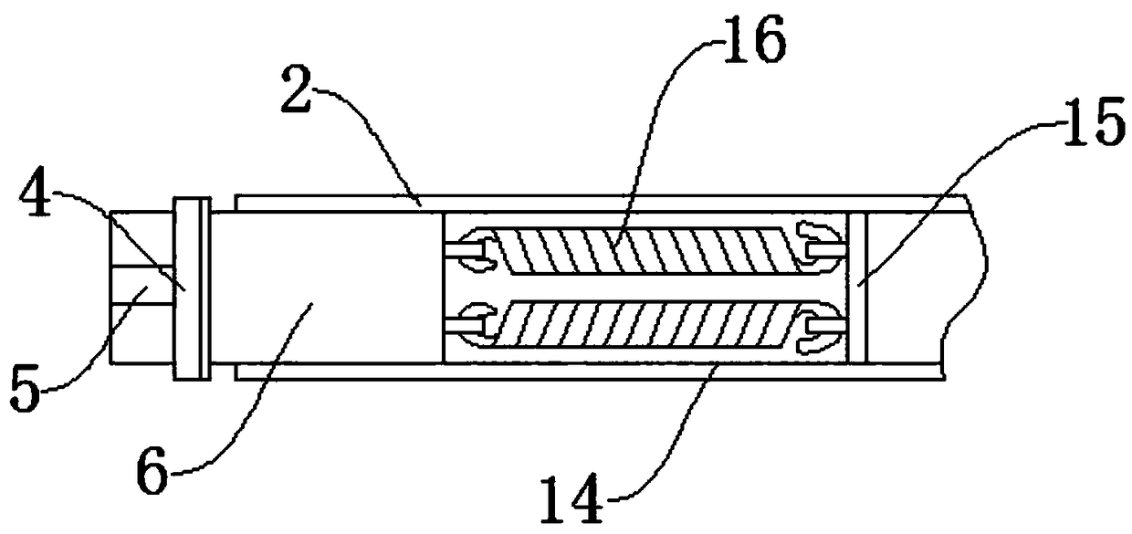
[0031] like Figure 1-Figure 5 As shown, a slotting device for the production of antistatic aramid composite flooring includes a slotting knife 1 and a base 2. A lower installation groove 14 is formed inside the lower end of the base 2, and an internal fixing groove 14 is arranged inside the lower installation groove 14. Plate 15, a return spring 16 is provided on one side of the internal fixing plate 15, a slider 6 is provided on one side of the return spring 16, a handle 7 is provided above the outer end of the slider 6, and a handle 7 is provided on the outer end of the slider 6. A support arm 5 is provided below the end, and a side splint 4 is provided at the end of the support arm 5, and an anti-skid pad 3 is provided on the side of the side splint 4, and a rack 25 is arranged above the base 2, and the rack 25 A hobbing 24 is arranged above, and a horizontal movement seat 8 is arranged above the hobbing 24. A horizontal movement motor 23 is provided on one side of the hor...

Embodiment 2

[0033] The difference between this embodiment and Embodiment 1 is:

[0034]In this embodiment, the internal fixing plate 15 is welded to both ends of the lower installation groove 14, the slider 6 is slidably connected in the lower installation groove 14, and the two ends of the return spring 16 are respectively hooked on On the internal fixing plate 15 and the sliding block 6, at least two returning springs 16 are arranged between the internal fixing plate 15 and the sliding block 6, and the returning springs 16 are always in a stretched state.

[0035] Specifically, such setting can be fixed by utilizing the elastic force of the return spring 16 .

[0036] The present invention also provides a method for using the slotting device for the production of antistatic aramid composite flooring, which is applied to the above slotting device for the production of antistatic aramid composite flooring. When in use, hold the handle 7 and stretch it outward, so that The two side splint...


PUM


Abstract

The invention discloses a slotting device for producing an antistatic aramid composite floor and a method of using the slotting device. The slotting device comprises a slotting knife and a base, wherein a lower mounting groove is formed inside the lower end of the base, an inner fixing plate is disposed in the lower mounting groove, a return spring is disposed on one side of the inner fixing plate, and a sliding block is disposed on one side of the return spring. A handle is disposed above the outer end of the sliding block, a support arm is disposed below the outer end of the sliding block, and a side splint is disposed at an end of the support arm. An anti-slip mat is disposed on a side of the side splint, and a rack is disposed above the base. A gear hobbing is disposed above the rack,a horizontal moving seat is disposed above the gear hobbing, and a horizontal moving motor is disposed on one side of the horizontal moving seat. The beneficial effects include that 1. the structure is simple, the installation and fixing are convenient, and the transportation and use are convenient; 2. the slotting depth and length can be precisely controlled through control by a servo motor, andslotting at different positions on the floor is convenient.

Description

technical field [0001] The invention relates to the technical field of floor processing equipment, in particular to a slotting device for antistatic aramid composite floor production and a method for using the same. Background technique [0002] Anti-static aramid composite flooring is a new type of flooring. It needs to be grooved on its edge and back during use to prevent it from swelling due to thermal expansion and contraction, which will affect the flatness of the ground. [0003] Chinese patent application number CN201420308096.3, a floor slotting device, including a push mechanism on the workbench for pushing the floor to the cutting knife, two guide plates for guiding the cutting knife to slot, and the cutting knife, The two guide plates are arranged in parallel on both sides of the grooved position of the floor, and are provided with supporting bases, and the bases are connected with bent plates for positioning the bases on both sides of the floor. [0004] The slo...

Claims


Application Information

Patent Timeline
Patent Type & Authority Applications(China)
IPC IPC(8): B27F5/00
CPCB27F5/00
Inventor 刘彪
Owner 鑫材泰克(天津)复合材料有限公司
Why Eureka
Try Eureka