High-temperature plate conveying channel, conveyor and sinter cooling system

A technology of high-temperature plates and conveying troughs, applied in the fields of conveyors and sinter cooling systems, high-temperature plate conveying troughs, metallurgical sinter conveying systems and cooling systems, can solve problems such as deformation and uncontrolled opening angles, and achieve Large heat preservation area, reducing heat radiation and preventing mutual contact

Pending Publication Date: 2019-01-15
ZHONGYE-CHANGTIAN INT ENG CO LTD
View PDF15 Cites 0 Cited by
  • Summary
  • Abstract
  • Description
  • Claims
  • Application Information

AI Technical Summary

Problems solved by technology

[0006] Aiming at the problems existing in the prior art, the present invention provides a high-temperature plate conveying trough, a conveyor and a sinter cooling system, which can reduce the heat loss at the bottom and both sides during the transportation of high-temperature materials, and combine them in the upper part of the conveying trough The heat preservation cover is set to keep the heat of the high-temperature sinter as much as possible until it enters the vertical cooler, and the heat can be more effectively recovered for power generation; at the same time, it solves the uncontrolled opening angle between the conveying chains of the traditional slat conveyor and the process of transporting materials. The problem that may cause the conveying troughs to contact each other and deform under force can reduce the leakage of the conveyor and reduce the deformation of the conveying trough during transportation, thereby prolonging the service life of the conveying trough and the service life of the conveyor

Method used


Image

  • High-temperature plate conveying channel, conveyor and sinter cooling system
  • High-temperature plate conveying channel, conveyor and sinter cooling system
  • High-temperature plate conveying channel, conveyor and sinter cooling system

Examples


Embodiment approach

[0061] According to a first embodiment of the present invention, a high-temperature plate conveyor trough is provided.

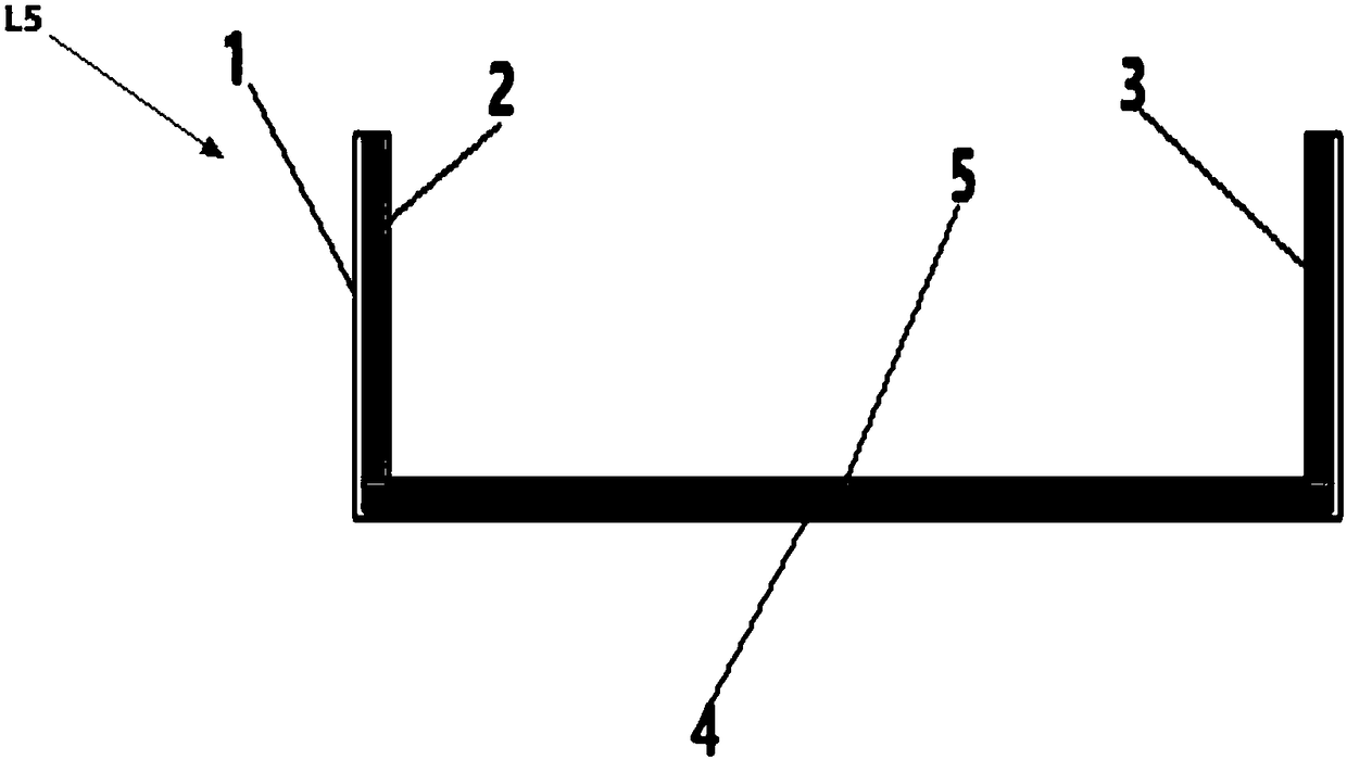
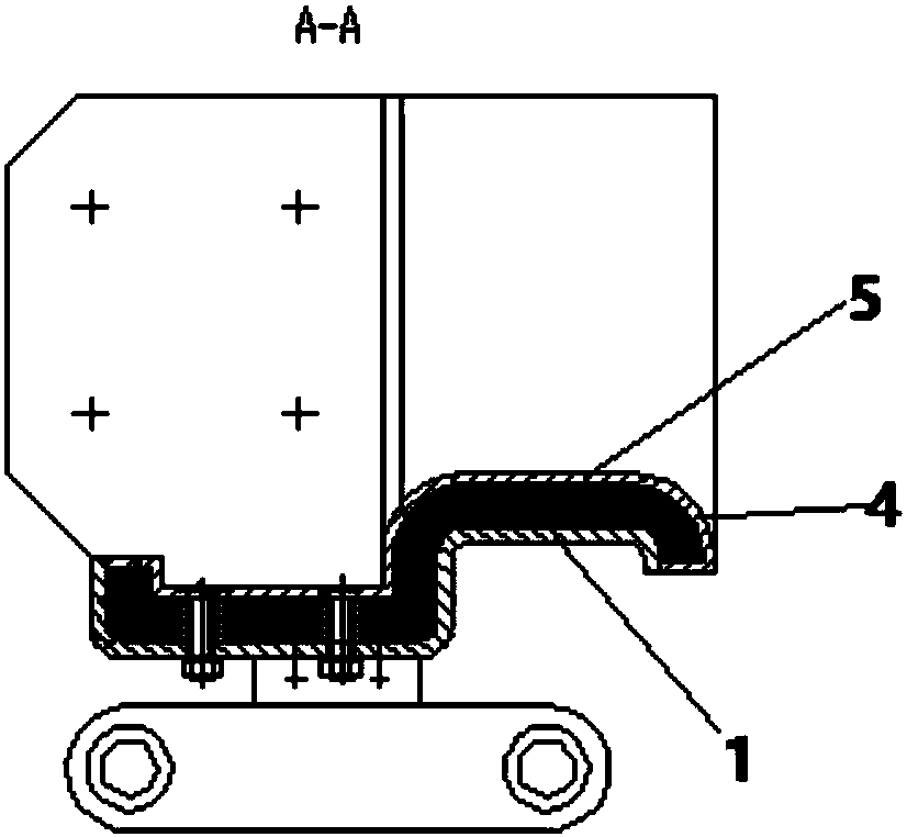
[0062] A high-temperature plate-type conveying tank L5, the high-temperature plate-type conveying tank L5 includes a tank body 1, a side heat-insulating material layer 2, a side cover plate 3, a bottom heat-insulating material layer 4, and a bottom cover plate 5. Wherein: the tank body 1 is a "U" shape or a concave structure. The tank body 1 has a bottom surface and two side surfaces. A side insulation material layer 2 is provided on the inner surface of the side of the tank body 1 . A side cover plate 3 is provided on the surface of the side heat insulating material layer 2 . The surface of the bottom surface of the tank body 1 is provided with a bottom insulation material layer 4 . A bottom cover plate 5 is provided on the surface of the bottom insulating material layer 4 . The bottom end of the side cover 3 is connected to the bottom cover 5 .

[006...

Embodiment 1

[0083] Such as Figure 1-3As shown, a high-temperature plate conveying tank L5 includes a tank body 1 , a side insulation material layer 2 , a side cover 3 , a bottom insulation material layer 4 , and a bottom cover 5 . Wherein: the tank body 1 is a "U" shape or a concave structure. The tank body 1 has a bottom surface and two side surfaces. A side insulation material layer 2 is provided on the inner surface of the side of the tank body 1 . A side cover plate 3 is provided on the surface of the side heat insulating material layer 2 . The surface of the bottom surface of the tank body 1 is provided with a bottom insulation material layer 4 . A bottom cover plate 5 is provided on the surface of the bottom insulating material layer 4 . The bottom end of the side cover 3 is connected to the bottom cover 5 .

[0084] The side insulation material layer 2 and the bottom insulation material layer 4 are heat-resistant fiber felt layers. The side cover 3 and the bottom cover 5 are...

Embodiment 2

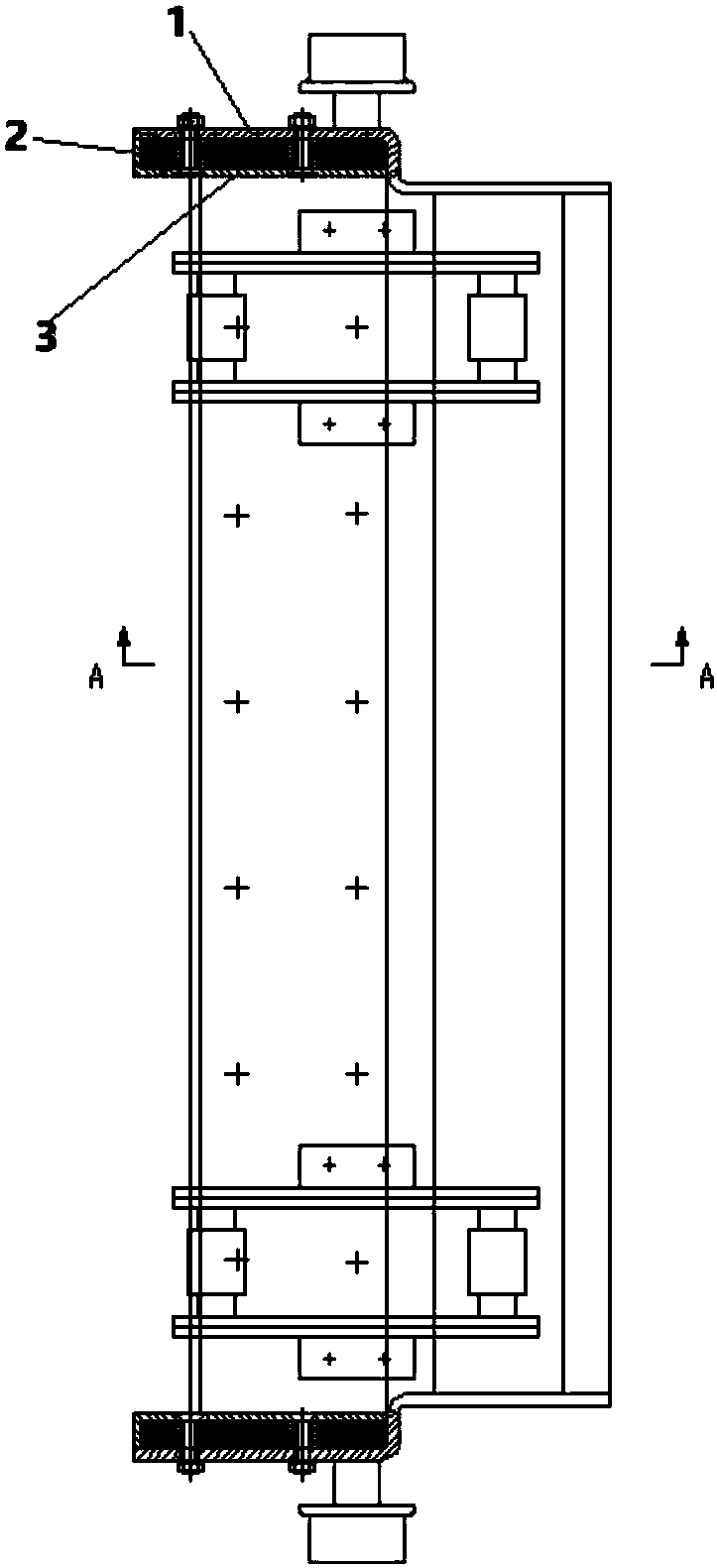
[0086] Such as Figure 4-13 As shown, a high-temperature apron conveyor S1, the high-temperature apron conveyor S1 includes the high-temperature apron conveying trough L5 of Embodiment 1, and also includes: a top heat preservation cover 6, a pillar 7, a beam 8, a lower support 9, and an upper driving device 10 , The lower driving device 11 and the chain L of the self-locking slat conveyor. Wherein: the top insulation cover 6 is arranged on the top of the pillar 7 . The middle part of the pillar 7 is provided with a beam 8 . An upper driving device 10 is provided on the beam 8 . The lower end of the pillar 7 is provided with a lower bracket 9 . A lower driving device 11 is provided on the lower bracket 9 . The self-locking slat conveyor chain L is connected with the upper driving device 10 and the lower driving device 11 . The upper driving device 10 and the lower driving device 11 drive the chain L of the self-locking slat conveyor to perform rotary motion. The chain L o...


PUM

PropertyMeasurementUnit
thicknessaaaaaaaaaa
thicknessaaaaaaaaaa
widthaaaaaaaaaa

Abstract

The invention relates to a high-temperature plate conveying channel (L5) which comprises a channel body (1), side thermal insulating material layers (2), side cover plates (3), a bottom thermal insulating material layer (4) and a bottom cover plate (5), wherein the channel body (1) is of a U-shaped or concave structure, and is provided with a bottom surface and two side surfaces; the side thermalinsulating material layers (2) are arranged on the inner surfaces of the side surfaces of the channel body (1); the side cover plates (3) are arranged on the surfaces of the side thermal insulating material layers (2); the bottom thermal insulating material layer (4) is arranged on the surface of the bottom surface of the channel body (1); the bottom cover plate (5) is arranged on the surface of the bottom thermal insulating material layer (4); and the bottom ends of the side cover plates (3) are connected with the bottom cover plate (5). Heat losses of high-temperature materials at the bottomand on the two sides in the conveying process are reduced, material leakage of a conveyor is reduced, and deformation of the conveying channel in the conveying process is reduced, so that the life cycle of the conveying channel is prolonged, and the service life of the conveyor is also prolonged.

Description

technical field [0001] The invention relates to a metallurgical sinter transport system and a cooling system, in particular to a high-temperature plate-type conveying trough, a conveyor and a sinter cooling system, belonging to the field of metallurgical sinter devices. Background technique [0002] The slat conveyor is a conveying device that uses a closed, cyclically running chain as the traction member, and uses butt or lapped parallel plates, corrugated plates, and trough or box-shaped components as the load-bearing components. Apron conveyors are suitable for conveying both bulk materials and finished items. It has been widely used in metallurgy, coal, chemical industry, electric power, machinery manufacturing and other industrial sectors of the national economy. [0003] In the traditional sintering process, there are two parts of waste heat resources: sensible heat of sintering ore (exhaust gas of ring cooler) and sensible heat of flue gas of sintering machine. Sint...

Claims


Application Information

Patent Timeline
Patent Type & Authority Applications(China)
IPC IPC(8): B65G17/38B65G23/24B65G17/30C22B1/16C22B1/26F27D3/00F27D15/02
CPCF27D3/00F27D15/0266C22B1/16C22B1/26B65G17/30B65G17/38B65G23/24
Inventor 吴学兵贺新华肖中元张震
Owner ZHONGYE-CHANGTIAN INT ENG CO LTD
Why Eureka
Try Eureka