A high-efficiency air flotation device for sewage treatment

A sewage treatment, high-efficiency technology, applied in flotation water/sewage treatment, water/sludge/sewage treatment, water treatment parameter control, etc., can solve the problem of low contact probability, increased contact between air bubbles and solid particles, and low air flotation efficiency and other problems, to achieve the effect of uniform purification treatment, high-efficiency purification treatment, and improvement of practicability

Active Publication Date: 2021-04-16
SICHUAN JINMEI ENVIRONMENTAL PROTECTION TECH
View PDF10 Cites 0 Cited by
  • Summary
  • Abstract
  • Description
  • Claims
  • Application Information

AI Technical Summary

Problems solved by technology

[0003] However, the structure of the existing air flotation device is simple. When treating sewage, the tiny air bubbles at the bottom of the air flotation tank directly move upward in the sewage. Since the buoyancy of the air bubbles is greater than the gravity and the resistance of the water, during the process of floating, the air bubbles The speed gradually increases, so that the bubbles stay in the sewage for less time, and it is difficult to fully contact the solid suspended particles in the sewage. Therefore, the air flotation machine is required to generate a large number of bubbles to increase the contact between the bubbles and the solid particles, and because the contact probability is small, It leads to low air flotation efficiency. Not only that, when the existing air flotation device is in use, sewage must be introduced into the air flotation tank to reach a fixed liquid level. When the sewage liquid level is too low or too high, the slag scraper cannot be used. The scum on the sewage liquid surface further reduces the practicability of the existing air flotation device

Method used


Image

  • A high-efficiency air flotation device for sewage treatment
  • A high-efficiency air flotation device for sewage treatment
  • A high-efficiency air flotation device for sewage treatment

Examples


Embodiment Construction

[0024] The present invention is described in further detail now in conjunction with accompanying drawing. These drawings are all simplified schematic diagrams, which only illustrate the basic structure of the present invention in a schematic manner, so they only show the configurations related to the present invention.

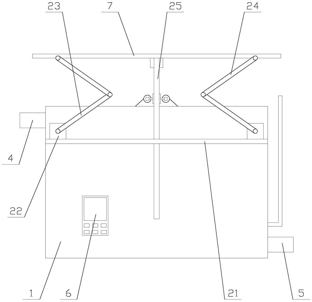
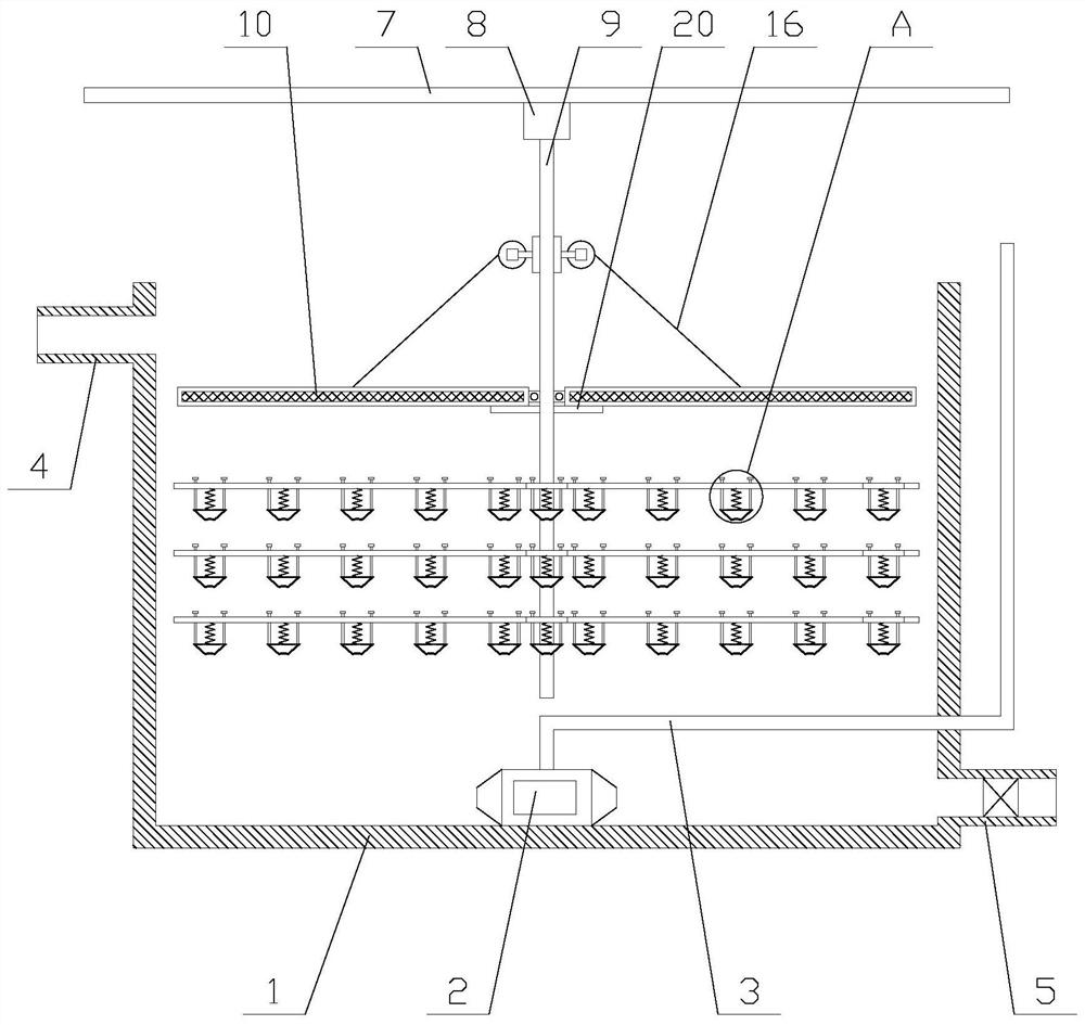
[0025] Such as Figure 1-2 As shown, a high-efficiency air flotation device for sewage treatment includes an air flotation tank 1, an air flotation machine 2, an air inlet pipe 3, a water inlet pipe 4, an outlet pipe 5, a controller 6, a top plate 7, a lifting mechanism, and a first motor 8. Rotating shaft 9, two filter mechanisms and several deceleration mechanisms, the water inlet pipe 4 and the water outlet pipe 5 are respectively fixed on both sides of the air flotation pool 1, the water outlet pipe 5 is provided with a valve, and the air flotation machine 2 is fixed At the bottom in the air flotation pool 1, the controller 6 is fixed on the air flotation...


PUM


Abstract

The invention relates to a high-efficiency air flotation device for sewage treatment, which includes an air flotation tank, an air flotation machine, an air inlet pipe, a water inlet pipe, a water outlet pipe, a controller, a top plate, a lifting mechanism, a first motor, a rotating shaft, and two filtering mechanisms and a number of deceleration mechanisms, the filter mechanism includes a filter screen, a flat plate and a shrinking assembly, the shrinking assembly includes a second motor and two shrinking units, the shrinking unit includes a bearing, a transmission shaft, a reel and a pull wire, the deceleration mechanism includes several deceleration assemblies, the deceleration assembly Including horizontal plates and several deceleration units, the high-efficiency air flotation device for sewage treatment reduces the rising speed of bubbles in water through the deceleration mechanism, so that the bubbles have enough time to contact and drive the solid particles in the sewage to float up, so as to achieve efficient purification Treatment, not only that, the filter mechanism makes the scum stay on the surface of the filter screen during drainage, which is convenient for people to clean up the scum and achieve the purpose of solid-liquid separation, thereby improving the practicability of the equipment.

Description

technical field [0001] The invention relates to the field of water pollution control equipment, in particular to an efficient air flotation device for sewage treatment. Background technique [0002] Air flotation is an abbreviation of air flotation machine, and it can also be used as a proper noun, that is, the air flotation method in water treatment, which is to form highly dispersed micro-bubbles in water and adhere to solids or liquids with hydrophobic groups in wastewater. Particles form a three-phase mixed system of water, air and particles. After the particles adhere to the air bubbles, they form flocs with an apparent density lower than that of water and float to the water surface, forming a scum layer that is scraped off, thereby realizing solid-liquid or liquid-liquid separation. process. [0003] However, the structure of the existing air flotation device is simple. When treating sewage, the tiny air bubbles at the bottom of the air flotation tank directly move up...

Claims


Application Information

Patent Timeline
Patent Type & Authority Patents(China)
IPC IPC(8): C02F1/24
CPCC02F1/24C02F2209/005
Inventor 刘洋
Owner SICHUAN JINMEI ENVIRONMENTAL PROTECTION TECH
Why Eureka
Try Eureka