
Side-blowing spray gun for melting furnace and application method thereof

A smelting furnace and spray gun technology, applied in combustion methods, furnaces, crucible furnaces, etc., can solve the problems of short service life, poor safety performance, and easy burning of spray guns, and achieve improved melting efficiency, improved service life, and good combustion effects Effect

Active Publication Date: 2019-01-15
JIANGSU NEW CHUNXING RESOURCE RECYCLING CO LTD
View PDF5 Cites 3 Cited by
  • Summary
  • Abstract
  • Description
  • Claims
  • Application Information

AI Technical Summary

Problems solved by technology

[0006] The purpose of the present invention is to provide a side-blowing spray gun for melting furnace and its usage method, which can solve the problems of short service life, easy burning and poor safety performance of the spray gun

Method used


Image

  • Side-blowing spray gun for melting furnace and application method thereof
  • Side-blowing spray gun for melting furnace and application method thereof
  • Side-blowing spray gun for melting furnace and application method thereof

Examples


Embodiment 1

[0037] Embodiment 1: including side blowing spray gun and the using method of side blowing spray gun.

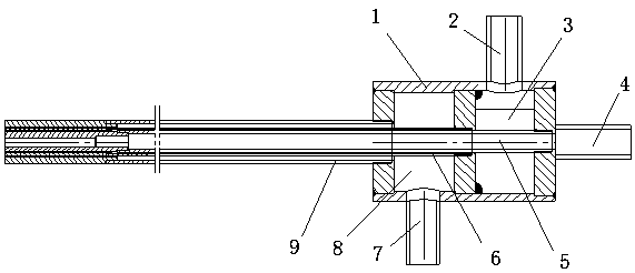
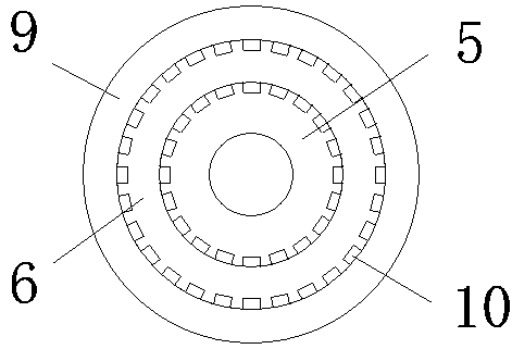
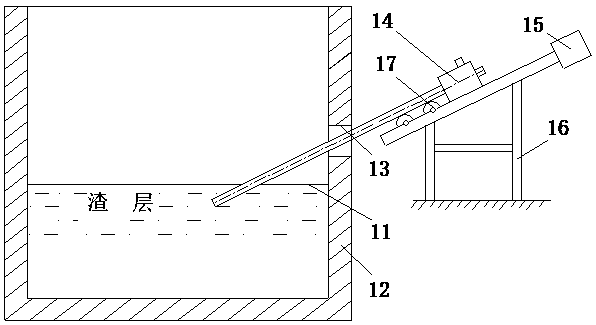
[0038]The side blowing spray gun includes: gas collector 1, combustible gas inlet 2, combustible gas chamber 3, oxygen or oxygen-enriched air inlet 4, oxygen or oxygen-enriched air pipe 5, combustible gas pipe 6, compressed cooling air inlet 7, compressed cooling air chamber 8 and compressed cooling air pipe 9; there are combustible gas chamber 3 and compressed cooling air chamber 8 in the gas collection cylinder 1; combustible gas inlet 2, oxygen or oxygen-enriched air inlet 4 and compressed cooling air inlet 7 are connected to the gas collection cylinder, oxygen or The oxygen-enriched air inlet 4 is located at one end of the gas collector 1, and the combustible gas inlet 2 and the compressed cooling air inlet 7 are correspondingly connected to the combustible gas chamber 3 and the compressed cooling air chamber 8; the oxygen or oxygen-enriched air pipe 5 passes through the ...

Embodiment 2

[0054] Embodiment 2: be the embodiment that manually feeds the side blowing spray gun, other is the same with embodiment 1.


PUM


Abstract

The invention relates to a side-blowing spray gun for a melting furnace and an application method thereof, and belongs to a side-blowing spray gun and an application method thereof. According to the invention, a gas connecting cylinder of the side-blowing spray gun is internally provided with a combustible gas chamber and a compressed cooling air chamber; the gas collecting cylinder is connected with a combustible gas inlet, an oxygen inlet and a compressed cooling air inlet, the oxygen inlet is located at one end of the gas collecting cylinder, and the combustible gas inlet and the compressedcooling air inlet are correspondingly connected at the positions of the combustible gas chamber and the compressed cooling air chamber; an oxygen pipe is sleeved in a combustible gas pipe, the oxygenpipe and the combustible gas pipe are sleeved in a compressed cooling air pipe, and there is a gap between the pipes; the oxygen pipe penetrates through the gas collecting cylinder, is connected to the gas collecting cylinder at the position of the oxygen inlet and is communicated with the oxygen inlet; the combustible gas pipe penetrates through the gas collecting cylinder and is connected to apartition between the combustible gas chamber and the compressed cooling air chamber; the compressed cooling air pipe is connected to the bottom end of the gas collecting cylinder; and the other end is a gas output end of the spray gun. The side-blowing spray gun has the advantages of long service life, simple structure, low cost, convenient operation, high stirring power of a molten pool, good effect and low energy consumption.

Description

technical field [0001] The invention relates to a side-blowing spray gun and a using method, in particular to a side-blowing spray gun for a smelting furnace and a using method. Background technique [0002] After more than 20 years of development, the side-blown molten pool smelting technology has become a new and mature smelting process with mature and reliable technology, high efficiency and low consumption, strong adaptability to raw materials, environmental protection and outstanding economic benefits. In particular, this technology has the advantages of simple process, convenient operation, large production capacity and low investment, and has been widely promoted and applied in our country. [0003] Chinese patent "Non-ferrous metal smelting side-blowing furnace spray gun", patent number: 2008102246301, discloses "the spray gun body of the sleeve structure and the spray gun head at the front end of the spray gun body, and the central pipe of the sleeve structure has a...

Claims


Application Information

Patent Timeline
Patent Type & Authority Applications(China)
IPC IPC(8): F27B14/08F27B14/14F27B14/20F27D19/00F27D27/00F27D99/00F23D14/22F23D14/78
CPCF23D14/22F23D14/78F27B14/08F27B14/14F27B14/20F27D19/00F27D27/00F27D99/0033F27D2099/0036F27D2027/002F27D2019/0043F27D2019/0056F27D2019/004F27B2014/0837F23D14/52F27D3/16F27D2003/168F27D2003/169C21C5/4606Y02P10/32
Inventor 杨春明杨大伟
Owner JIANGSU NEW CHUNXING RESOURCE RECYCLING CO LTD
Learn More