Distributed array target angle measurement method for high frequency ground wave radar

A high-frequency ground wave radar and target angle technology, which is applied in radio wave measurement systems, measurement devices, radio wave reflection/reradiation, etc., can solve the problem of strong coherence of echo signals, increased hardware costs, and difficult performance adjustments and other problems, to achieve the effect of fewer targets, saving hardware costs, and improving performance

Active Publication Date: 2022-07-01
HARBIN INST OF TECH
View PDF2 Cites 0 Cited by
  • Summary
  • Abstract
  • Description
  • Claims
  • Application Information

AI Technical Summary

Problems solved by technology

In order to improve the performance of direction finding, an angle measurement method based on modern super-resolution spectrum estimation technology was proposed. However, due to the particularity of the high-frequency radar system with a large number of targets and unknown numbers, and strong coherence of echo signals, such methods cannot The application is still subject to many limitations, such as the need to know the number of targets, and the de-correlation interprocessing step when processing coherent signals requires a specific array form, etc.
Although some direction finding methods based on sparse representations that have emerged in recent years can solve the above problems, their limitations are that their performance largely depends on one or more adjustable hyperparameters. In the actual situation of unknown noise variance It is difficult to adjust this parameter to the optimum to obtain satisfactory performance
In addition, in order to further improve the angle measurement performance, the traditional radar array needs more receiving elements to increase the array aperture, but this will lead to harsh site requirements and significantly increase hardware costs

Method used


Image

  • Distributed array target angle measurement method for high frequency ground wave radar
  • Distributed array target angle measurement method for high frequency ground wave radar
  • Distributed array target angle measurement method for high frequency ground wave radar

Examples


Embodiment

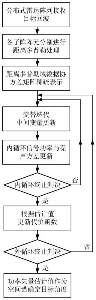
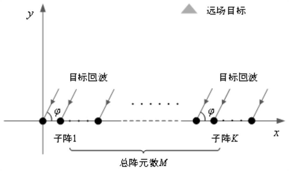
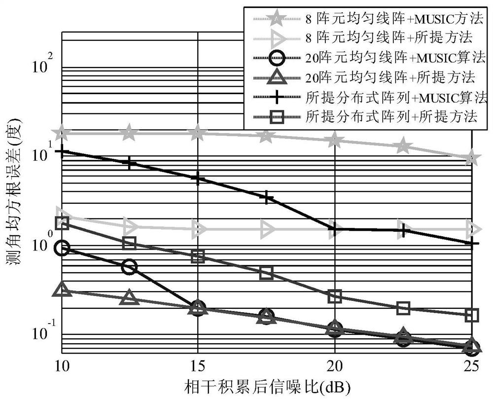
[0117] The mean square error curve of angle measurement obtained by the proposed distributed array target angle measurement method for high-frequency ground wave radar is as follows: image 3 The simulation conditions are as follows: the radar transmit signal is a chirp interrupted continuous wave, the carrier frequency is 3MHz, the bandwidth is 75KHz, the frequency modulation period is 200ms, the pulse repetition period is 4ms, the pulse width is 0.4ms, and the sampling frequency is 37.5KHz. The total number of FM cycles used for coherent accumulation of each batch of echo data is 500, and the accumulation time is 100s; the receiving array includes a 20-element uniform line array with an array element spacing of half a wavelength, an 8-element uniform line array, and figure 1 The distributed array proposed by the present invention is shown, the distributed array has the same aperture as the 20-element uniform linear array, but it is composed of two 4-element sub-arrays, and th...


PUM


Abstract

The invention proposes a distributed array target angle measurement method for high-frequency ground wave radar, which is characterized by comprising: step 1, receiving echo distance Doppler processing of each sub-array element of the radar; step 2, data coordination Variance matrix sparse representation modeling; step 3, transformation of the optimization problem to be solved; step 4, update signal power estimation value in inner loop; step 5, update cost function in outer loop and finally obtain target angle estimation; The distributed array adopted is flexible in layout, convenient in location selection, and only needs a small number of array elements to achieve the direction finding performance of a traditional array with a larger aperture; and the angle measurement method proposed by the present invention requires at least a single distance Doppler domain. The second snapshot, no need to know the number of targets and any manual parameter adjustment, the direction finding performance is also significantly better than the traditional radar angle measurement method.

Description

technical field [0001] The invention relates to the technical field of radar target angle measurement, in particular to a distributed array target angle measurement method for high-frequency ground wave radar. Background technique [0002] Radar target angle measurement technology is an important research topic in the field of radar signal processing. Traditional high-frequency radar angle measurement generally still uses beamforming technology, but limited by the array aperture, its angle measurement accuracy and resolution are low. In order to improve the performance of direction finding, the angle measurement method based on modern super-resolution spectrum estimation technology is proposed. However, due to the large number of targets in the high-frequency radar system, the number is unknown, and the echo signal coherence is strong. The application is still subject to many limitations, such as the need to know the number of targets, and the decoherence and intervening pr...

Claims


Application Information

Patent Timeline
Patent Type & Authority Patents(China)
IPC IPC(8): G01S13/90G01S7/41
CPCG01S7/418G01S13/9011G01S13/9094
Inventor 马赫颜丽蝉赵春雷毛兴鹏
Owner HARBIN INST OF TECH
Why Eureka
Try Eureka