
Hilbert transform-based real signal Doppler frequency shifting method

A Doppler frequency shift, real signal technology, applied in the field of signal processing, can solve the problems of not covering the radio frequency band, difficult to eliminate, complex output signal spurious spectral lines, etc., to achieve great flexibility and reconfigurable characteristics, use Reduced, small size effect

Active Publication Date: 2019-01-15
UNIV OF ELECTRONIC SCI & TECH OF CHINA
View PDF4 Cites 0 Cited by
  • Summary
  • Abstract
  • Description
  • Claims
  • Application Information

AI Technical Summary

Problems solved by technology

However, due to the phase truncation effect of DDS, the finite word length effect of the sinusoidal lookup table, etc., the spurious spectral lines of the output signal will be complicated and difficult to eliminate, and this method can only realize the Doppler frequency shift of the intermediate frequency signal, and cannot cover high radio frequency band

Method used


Image

  • Hilbert transform-based real signal Doppler frequency shifting method
  • Hilbert transform-based real signal Doppler frequency shifting method
  • Hilbert transform-based real signal Doppler frequency shifting method

Examples


Embodiment

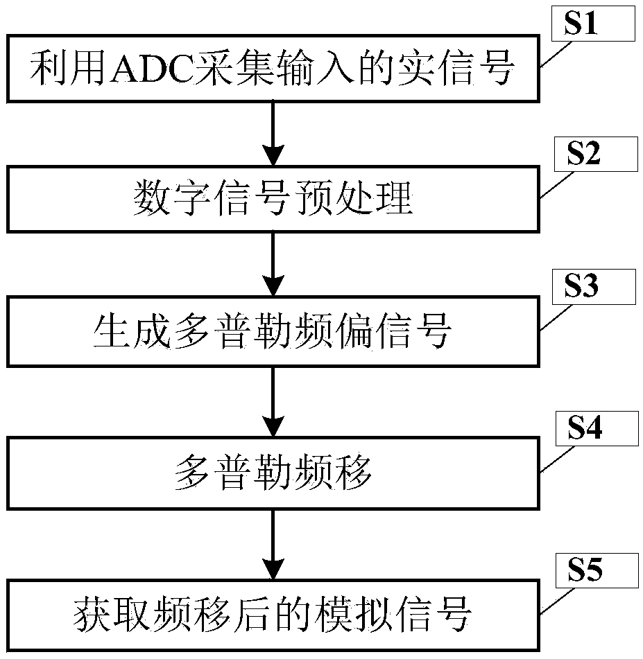
[0047] figure 2 The present invention is based on the flow chart of the real signal Doppler frequency shift method based on Hilbert transform.

[0048] In this example, if figure 2 Shown, a kind of real signal Doppler frequency shift method based on Hilbert transform of the present invention comprises the following steps:

[0049] S1, using ADC to collect the input real signal

[0050] Let the input real signal x(t) be the frequency f 0 The standard cosine signal of the sample rate f s The ADC is converted into a digital signal x(n) after sampling;

[0051]

[0052] S2, digital signal preprocessing

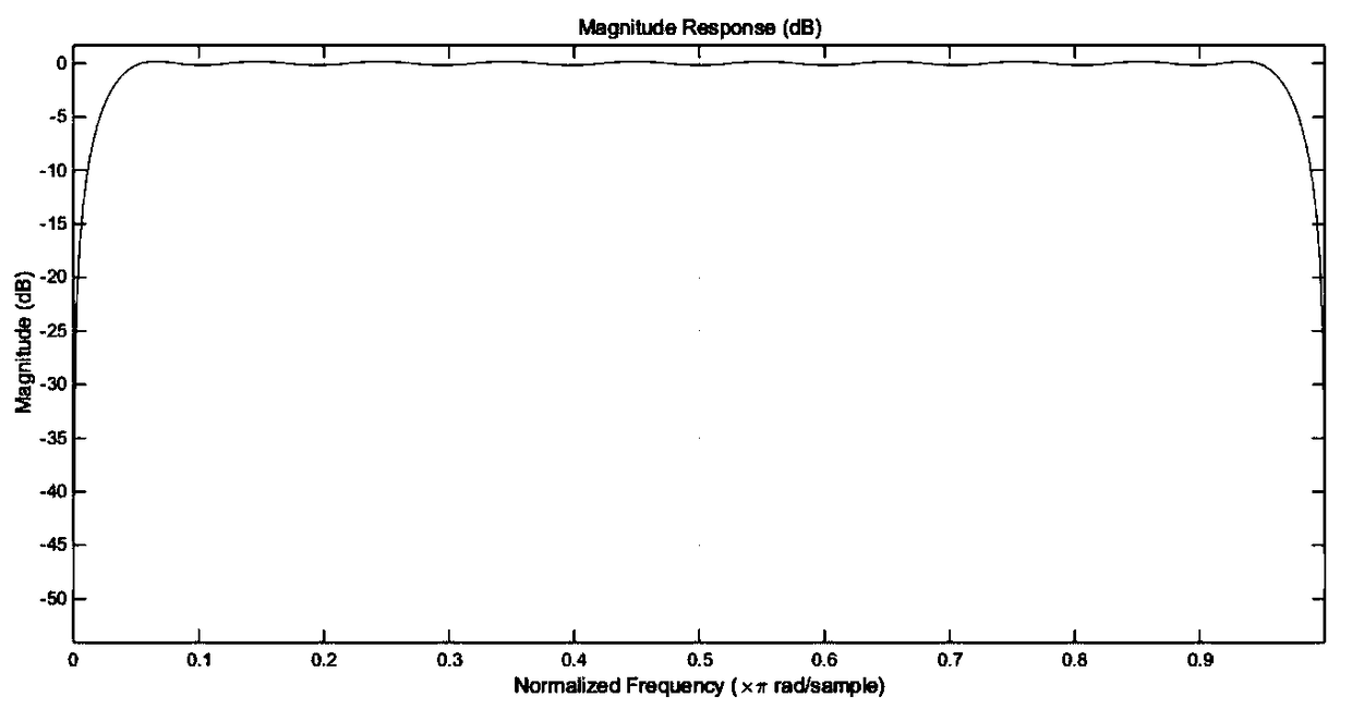
[0053] Input digital signal x(n) to FPGA and split into two parallel digital signals x 1 (n), x 2 (n), put x 1 (n) After Hilbert filter processing, the signal frequency remains unchanged, but the digital signal x with a phase lag of 90° 1 (n), and there exists K / f s Delay, K is determined by the length of the Hilbert filter coefficients, assuming a Hilbert digital fil...

example

[0081] Design a broadband signal transceiver module based on the PXIe bus, the operating frequency range is 65MHz-3GHz, and the instantaneous bandwidth is 800MHz. The module adopts the homodyne radio frequency transceiver scheme, and the baseband part adopts the hardware architecture with ADCs+FPGA+DACs as the core, and the structure has the size of 3 slots and 3U boards. The I / Q modulation and demodulator that can realize the instantaneous bandwidth of 800MHz in the existing market cannot cover the input frequency range of 65MHz to 3GHz required by the design. The design uses Linear's high-bandwidth I / Q demodulator LTC5586, which can receive IF signals and local oscillator signals in a frequency range of 300MHz-6GHz, and output I / Q signals with a 1dB bandwidth of 1GHz. For the reception of 65MHz-300MHz broadband intermediate frequency signals, the above scheme cannot be adopted, and must be processed separately. Direct conversion (I / Q) downconverters capable of receiving sig...


PUM


Abstract

The invention discloses a Hilbert transform-based real signal Doppler frequency shifting method. According to the method, firstly, the ADC is used to collect the input real signal. then divide the collected digital signal into two parts, Hilbert filter processing is carry out all that way, Then the Doppler frequency offset signals are generated by DDS Compiler IP core, and triangulated to obtain the Doppler frequency shifted digital signals. Finally, the Doppler frequency shifted analog signals are obtained by digital-to-analog conversion.

Description

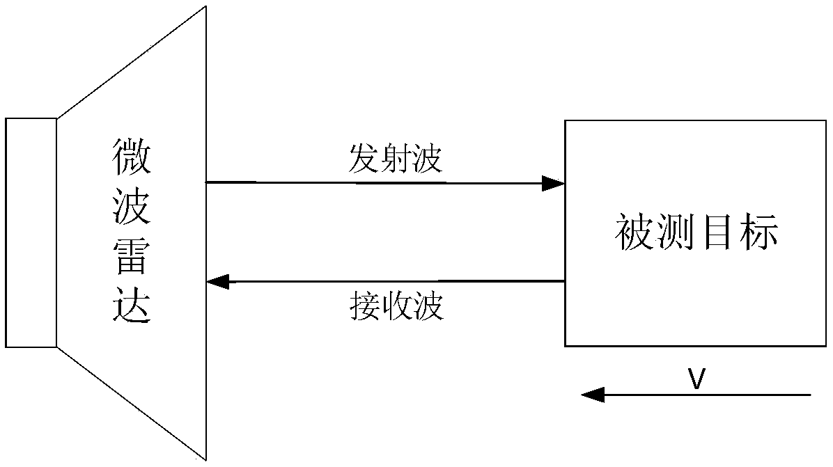
technical field [0001] The invention belongs to the technical field of signal processing, and more specifically relates to a real signal Doppler frequency shift method based on Hilbert transform. Background technique [0002] When there is radial relative movement between the wave source and the receiving object, the frequency of the received wave will change. When the wave source moves towards the receiving object, the frequency of the received wave becomes higher, and when the wave source moves away from the receiving object, the receiving frequency becomes lower. The frequency difference between the transmitted wave and the received wave is the Doppler frequency shift of the moving object. Radar uses Doppler frequency shift to obtain the moving speed of the target, so as to distinguish moving targets from stationary targets or clutter. [0003] Such as figure 1 As shown in , assuming that the target moves towards the radar direction with speed v, when the frequency of t...

Claims


Application Information

Patent Timeline
IPC IPC(8): H04L27/00
CPCH04L27/0014H04L2027/0026
Inventor 郭连平廖可曾浩杨佳千李煜郭祥巩
Owner UNIV OF ELECTRONIC SCI & TECH OF CHINA
Learn More