Method and system for pressure drop estimation

A technology of pressure difference and pipeline, applied in the field of estimation of blood pressure drop, which can solve problems such as ignoring viscous dissipation

Pending Publication Date: 2019-01-15
KINGS COLLEGE LONDON
View PDF6 Cites 4 Cited by
  • Summary
  • Abstract
  • Description
  • Claims
  • Application Information

AI Technical Summary

Problems solved by technology

This scheme benefits from the high temporal resolution of the data, but ignores effects related to advective acceleration outside the acoustic line and related to viscous dissipation

Method used


Image

  • Method and system for pressure drop estimation
  • Method and system for pressure drop estimation
  • Method and system for pressure drop estimation

Examples


no. 1 approach

[0033] First Embodiment: Full WERP

[0034] 2. Method

[0035] Starting from the work-energy principle, we obtain the formula for the pressure difference over the vessel section (section 2.1). Subsequently, we detail the discrete algorithms (Section 2.2) and preprocessing steps (Section 2.3) which are required to work with 4D PC-MRI data.

[0036] 2.1. Pressure difference from fluid work-energy

[0037] The pressure differential in a fluid system is related to the dynamics of the flow field. This relationship is described by the well-known Navier-Stokes equations in which, in the absence of gravity, changes in pressure are balanced by fluid acceleration and viscous stress. Work-energy generation for an incompressible isothermal Newtonian fluid over a region of interest (ROI) (Ω) with a boundary Γ using the conservation of mass and momentum for a closed system:

[0038]

[0039] where v represents the velocity, p represents the pressure, n is the normal vector on Γ, An...

no. 2 approach and no. 3 approach

[0099] Second and Third Embodiments: Full Advection WERP and Simplified Advection WERP

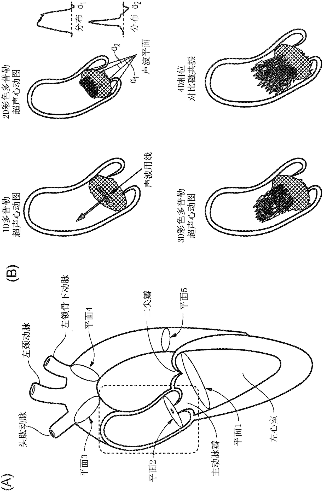
[0100] The second and third embodiments relate to simplifications of the full WERP process, which mean that less complex imaging modalities that acquire less information can be used. Specifically, as described below, the full advection WERP protocol can be performed using an arbitrary modality that renders velocity data (e.g., 2D PC MRI or 3D Doppler ECG) in two anatomical planes, while the simplified advection protocol can be performed with the rendered Any modality of velocity data (eg, 2D PC MRI, 3D Doppler ECG, or 2D Doppler ECG data) in a single anatomical plane is used together. Access to this portion of information (ie, velocity data in a single anatomical plane) is feasible with Doppler ECG imaging equipment that is very common in many clinical settings.

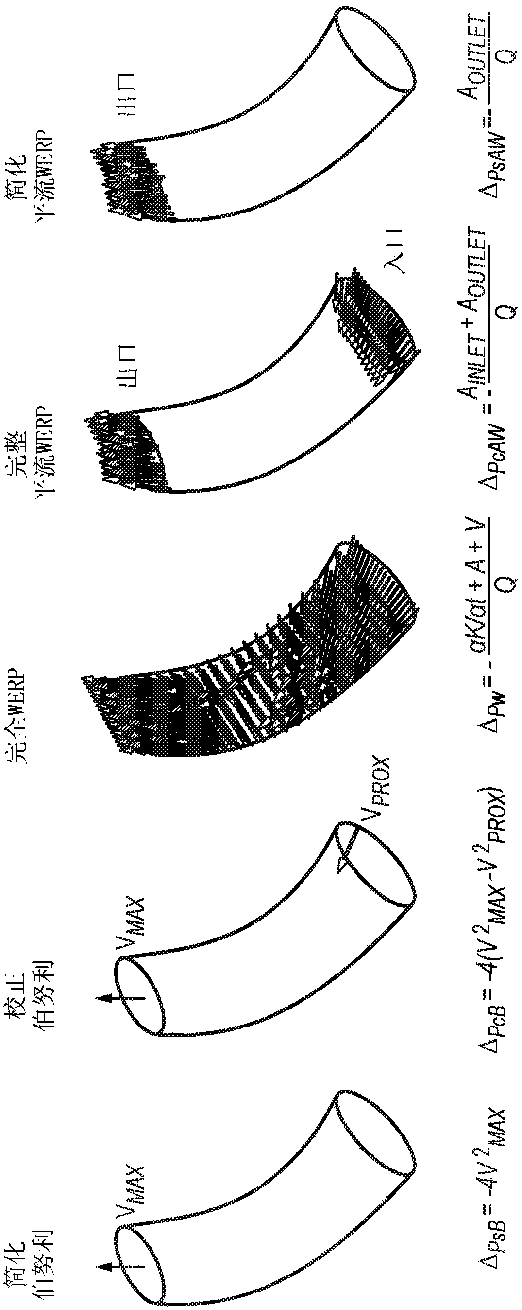
[0101] This is followed by a discussion of the scheme, presentation of various results, and a comparison with prior art Bern...

no. 2 Embodiment approach system

[0188] Second Embodiment System Description

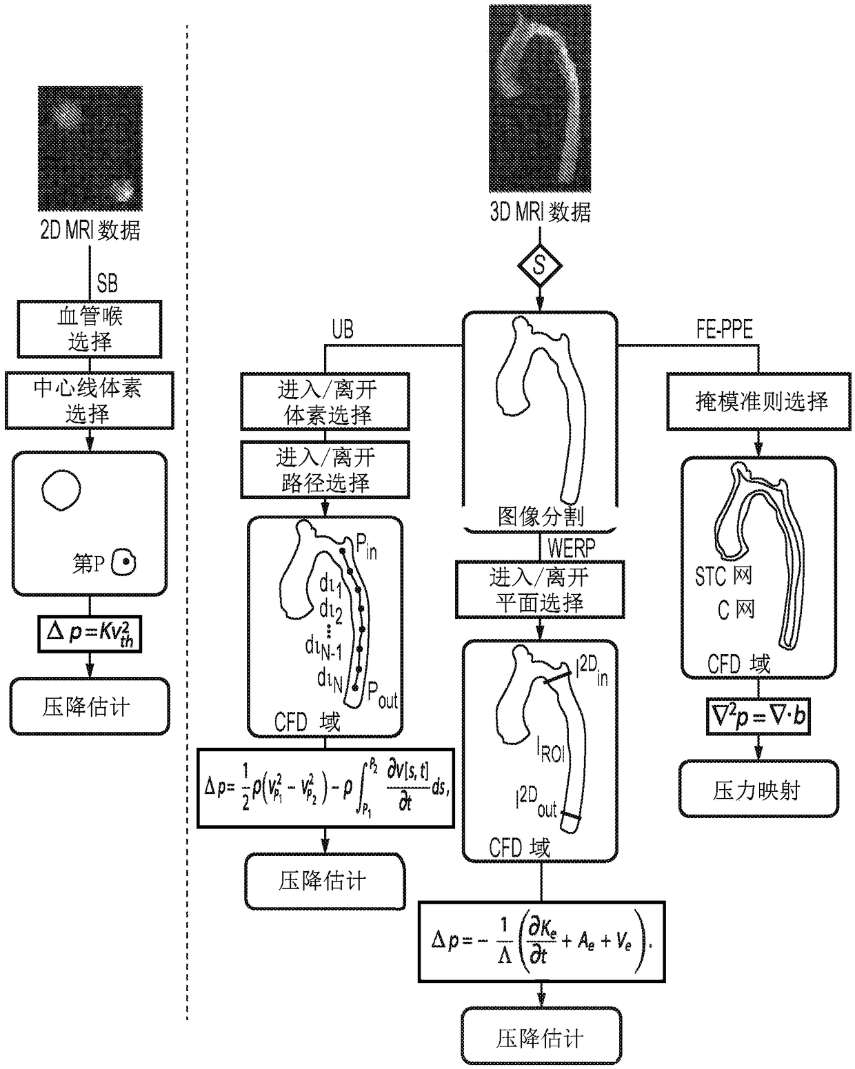
[0189]A second embodiment involves performing only a subset of WERP processing by considering only the advective term of the full WERP equation. Thus, less information is required and simpler imaging systems can be used, especially 2D PC MRI systems as well as 3D Doppler ECG systems. Figure 9 is a block diagram of a 2D MRI system that can be used to perform the process of calculating the pressure drop.

[0190] Here, a 2D phase-contrast magnetic resonance imaging (2D PC MRI) system 902 is provided, the system comprising MR imaging coils within which the subject is located, the coils being controlled by an MRI imaging control system 98 comprising MRI control Processor 90. The MRI imaging control system 98 including the MRI controller processor 90 functions in a conventional manner to allow acquisition of, for example, 3-dimensional phase contrast magnetic resonance imaging data of the internal vessels of a subject for whom pressu...


PUM


Abstract

Embodiments of the invention provide a method of determining pressure difference across a tube arising from fluid flow within the tube, comprising: obtaining three- dimensional time dependent fluid velocity data at a plurality of points along the tube; processing the three-dimensional time dependent fluid velocity data to determine: i) a flow rate (Q) of the fluid through the tube; ii) the kineticenergy (K) of the fluid flow through the tube; iii) an advective energy rate (A) of the fluid flow through the tube; and iv) a viscous dissipation rate (V) pertaining to the fluid flow; and calculating the pressure difference in dependence on all of the flow rate (Q), kinetic energy (K), advective energy rate (A), and viscous dissipation rate (V). Further embodiments are also described.

Description

technical field [0001] The present invention relates to methods and systems for estimating pressure drop through a circuit and, in particular embodiments, to estimation of blood pressure drop through a blood vessel based on measurements of velocity obtained from various medical imaging modalities. Background technique [0002] Pressure drop or pressure difference (also referred to as pressure gradient in some clinical literature) measured over a vessel segment is widely used clinically as a biomarker for a number of cardiovascular disorders (Baumgartner, Hung, Bermejo, Chambers, Evangelista , Griffin, Iung, Otto, Pellikka, 2009, Sawaya, Stewart, Babaliaros, 2012 and Vahanian, Baumgartner, Bax, Butchart, Dion, Filippatos, Flachskampf, Hall, Iung, Kasprzak, Nataf, Tornos, Torracca, Wenink, 2007). A well-known example is coarctation of the aorta (CoA), where pressure drop is used to risk stratify patients undergoing surgery (Jenkins, Ward, 1999 and Oshinski, Parks, Markou, Be...

Claims


Application Information

Patent Timeline
Patent Type & Authority Applications(China)
IPC IPC(8): A61B5/055A61B8/06A61B5/021A61B5/026A61B5/00
CPCA61B8/06A61B5/021A61B5/0263A61B5/055A61B5/7242A61B2576/023A61B8/488G16H30/40A61B8/04A61B8/5223
Inventor P·拉马塔·德·拉·奥尔登D·诺德斯勒藤F·多纳蒂N·史密斯
Owner KINGS COLLEGE LONDON
Why Eureka
Try Eureka