Full-automatic fruit picking device

A fully automatic, fruit technology, applied in picking machines, agricultural machinery and implements, applications, etc., can solve the problems of inability to ensure picking quality, inability to adapt to picking operations, low picking efficiency, etc., to ensure picking quality, ingenious design, and structure. simple effect

Pending Publication Date: 2019-01-18
HUBEI POLYTECHNIC UNIV
0 Cites 19 Cited by

AI-Extracted Technical Summary

Problems solved by technology

[0004] The technical problem to be solved by the present invention is to solve the problems that the existing mechanical picking devices are simple in structure, single in fun...

Method used

(2) Utilize the color image matching method based on limit constraint method and hue space to carry out the binocular stereoscopic matching of stem picking point, thereby realizing the spatial positioning of picking point.
Further, the rotary mechanism 10 described in the present embodiment has two bearing blocks 101 arranged on the top of the telescopic support frame 9 and arranged coaxially, and a rotary shaft 102 is equipped in the two bearing blocks 101, And one side of one of the bearing housings is equipped with a servo motor C103 arranged side by side with it, the output end of the servo motor C103 is equipped with a pinion 104, and a large gear 105 meshing with the pinion 104 is installed on the rotary shaft 102; The three-degree-of-freedom mechanical arm 11 includes a boom 111 and a small arm 112, one end of the boom 111 is connected to the rotary shaft 102, the other end of the boom 111 is equipped with a servo reduc...

Abstract

The invention discloses a full-automatic fruit picking device, which comprises a tracked vehicle. A fruit box and a control device are arranged on the tracked vehicle; a mobile base frame is also arranged on the tracked vehicle. The mobile base frame is provided with a XY axis mobile platform, and a telescopic support frame is vertically installed on the XY axis mobile platform; the top of the telescopic support frame is connected with one end of a three-degree-of-freedom mechanical arm through a rotary mechanism, and the other end of the three-degree-of-freedom mechanical arm is provided witha shearing manipulator; the shearing manipulator is provided with a base; the upper, middle and lower parts of the base are correspondingly provided with a binocular camera, a shearing cutter and a hanging ring which are horizontally arranged; the hanging ring is connect with the upper port of a soft bag; the lower port of the soft bag is extended into the fruit box, and multiple layers of anti-collision skirts are arranged in the soft bag. The full-automatic fruit picking device realizes the control of automatic navigation of the tracked vehicle. Besides, the automatic identification and positioning of target fruits are also realized in order to take picking into practice, which ensures the picking quality. The full-automatic fruit picking device has the advantages of high efficiency, feasibility, versatility and suitability for automatic picking of different fruits.

Application Domain

Technology Topic

Image

  • Full-automatic fruit picking device
  • Full-automatic fruit picking device
  • Full-automatic fruit picking device

Examples

  • Experimental program(2)

Example Embodiment

[0044] Example 1
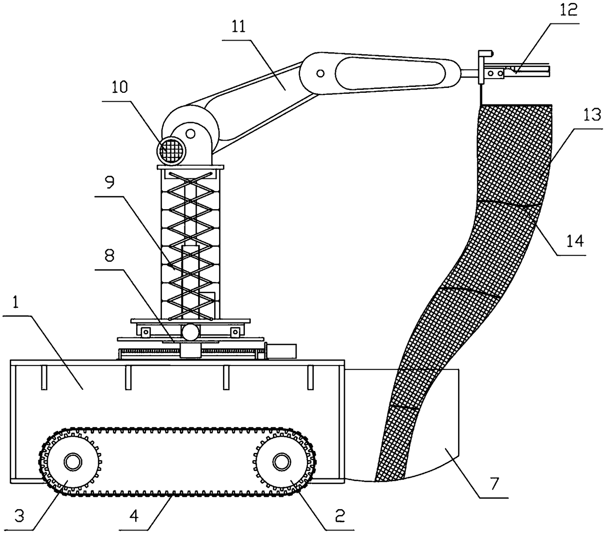
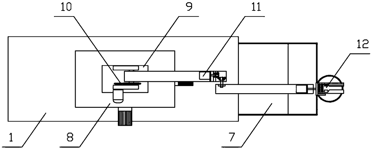
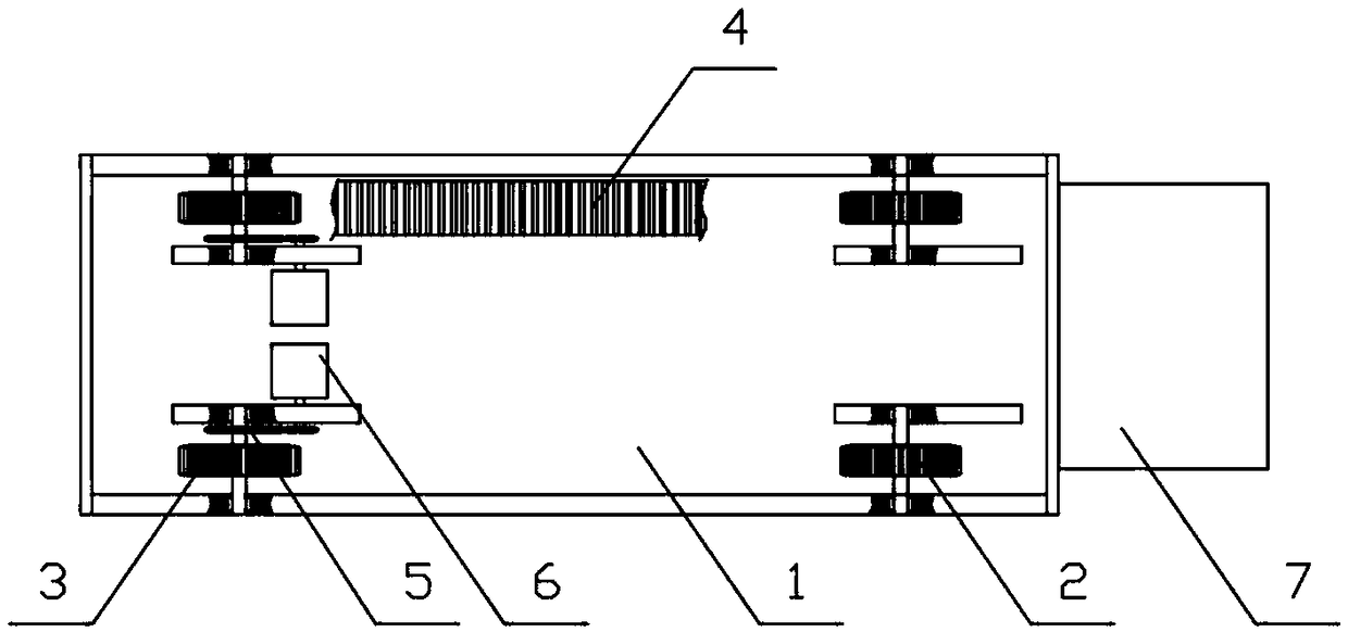
[0045] Such as Figure 1-10 As shown, the present invention provides a fully automatic fruit picking device with a crawler vehicle. The crawler vehicle is provided with an open fruit box 7 and a control device. The crawler vehicle is also provided with a mobile base frame. The mobile base frame has XY Axis mobile platform 8, XY axis mobile platform 8 is vertically equipped with a telescopic support frame 9; the top of the telescopic support frame 9 is connected to one end of the three-degree-of-freedom manipulator 11 through the slewing mechanism 10, and the other end of the three-degree-of-freedom manipulator 11 One end is equipped with a cutting operator 12; the cutting operator 12 has a base 121, and horizontally arranged binocular cameras 122, cutting tools and lifting rings 123 are installed on the upper, middle and lower parts of the base 121. The lifting ring 123 is connected to the upper port of the soft bag 13, and the lower port of the soft bag 13 extends into the fruit box 7, and several layers of anti-collision skirts 14 are provided in the soft bag 13.
[0046] The control device is composed of an upper main controller 15 and a lower walking controller 16, a mobile rack controller 17, and an end execution controller 18. The main controller 15 adopts an Advantech IPC610-H industrial computer, which is equipped with three One RS232 communication interface 20, used to respectively communicate with the mobile rack controller 17, the end execution controller 18 and the GPS monitoring receiver 19. The motion control card 21 is installed on the industrial computer, and through the matching with the motion control 21 The PCI bus communication is connected to the walking controller 16. The walking controller 16 adopts the Advantech PCI1240U model, and the industrial computer is connected to the binocular camera 122 through the equipped 1394 adapter card 22; the walking controller 16 is used to control the walking of the crawler The moving frame controller 17 is used to control the three-dimensional base coordinates of the three-degree-of-freedom manipulator 11 on the moving base frame, and the end execution controller 18 is used to control the movement of the three-degree-of-freedom manipulator 11. The current road image information and fruit tree image information captured by the binocular camera 122 are processed to extract visual navigation parameters and identify and locate the target fruit, thereby performing a picking operation on the target fruit.
[0047] Further, the crawler vehicle in this embodiment has a vehicle body 1, and the movable frame is installed on the upper side of the vehicle body 1. Two driven sprockets are correspondingly installed at the front and rear ends of the lower side of the vehicle body 1. 2 and two driving sprocket 3, and a set of driven sprocket 2 and driving sprocket 3 located on the left/right side of the car body 1 are equipped with crawlers 4, each driving sprocket 3 corresponds to a gear transmission mechanism 5 Connect the output terminal of the servo motor A6, and an encoder is equipped on the servo motor A6; the encoder is communicatively connected to the walking controller 16, and the walking controller 16 is based on the real-time feedback data from the encoder on each servo motor A6. The speed of the servo motor A6 is controlled in real time, and the walking controller 16 receives the visual navigation parameter information transmitted from the main controller 15 in real time, and realizes the control by adjusting the differential speed of the servo motor A6 corresponding to the two active sprockets 3 Real-time control of tracked vehicle walking dynamics.
[0048] Further, the XY-axis moving platform 8 in this embodiment is composed of an X-direction sliding table 801 and a Y-direction sliding table 802, wherein the Y-direction sliding table 802 is installed on the upper side of the X-direction sliding table 801; The table 801 and the Y-direction sliding table 802 are provided with a horizontal drive mechanism of the same structure. The horizontal drive mechanism includes a screw rod 804 and two horizontal guide rods 805 arranged side by side on the bottom plate 803. One end is connected to the output end of the servo motor B806, and a horizontal slider 807 matched with its thread is installed on the screw 804. The horizontal slider 807 is sleeved on the horizontal guide rod 805, and the horizontal slider 807 is installed for installation. The adapter plate 808 of the X-direction sliding table 801 or the Y-direction sliding table 802; the telescopic support frame 9 consists of an electric push rod 901 and a scissor bracket 902 arranged on the left and right sides of the electric push rod 901. The lifting end of the push rod 901 and the upper end of the scissor bracket 902 are respectively connected to the lifting base 903, and the base of the electric push rod 901 and the lower end of the scissor bracket 902 are connected to the XY axis moving platform 8; in order to further accurately control the X-direction sliding The table 801, the Y-direction sliding table 802 and the telescopic support 9 move in the X, Y, and Z directions respectively. Encoders are installed on the rotating motors of the two servo motors B806 and the electric push rod 901. The frame controller 17 receives the control instructions given by the main controller 15 in real time, and according to the real-time feedback data of the three encoders, realizes the precise control of the movement of the mobile base frame in the three directions of X, Y, and Z respectively.
[0049] Further, in this embodiment, the outer side of the telescopic support frame 9 is covered with a rubber sheath 904, the upper port of the rubber sheath 904 is connected to the lifting base 903, and each hinge point on the scissor bracket 902 passes through the soft The connection 905 is connected to the inner side wall of the rubber sheath, and the soft connection 905 can be cotton rope or nylon rope.
[0050] Further, the revolving mechanism 10 in this embodiment has two bearing seats 101 arranged on the top of the telescopic support frame 9 and arranged coaxially. The two bearing seats 101 are equipped with a rotating shaft 102, and One side of a bearing seat is equipped with a servo motor C103 arranged side by side with it, the output end of the servo motor C103 is equipped with a small gear 104, and a large gear 105 meshing with the small gear 104 is installed on the rotating shaft 102; the three degrees of freedom The robot arm 11 includes a big arm 111 and a small arm 112. One end of the big arm 111 is connected to the rotating shaft 102, the other end of the big arm 111 is equipped with a servo reduction motor A113, and the output end of the servo reduction motor A113 is equipped with a bevel gear A115. , The bevel gear A115 meshes with the bevel gear B116, the central hole of the bevel gear B116 is equipped with a central shaft 117, the center line of the servo reduction motor A113 intersects the central axis of the central shaft 117 perpendicularly; one end of the arm 112 is connected The central shaft 117, the other end of the arm 112 is equipped with a servo deceleration motor B114, and the output end of the servo deceleration motor B114 is connected to the base 121; in order to further accurately control the action of the three-degree-of-freedom manipulator 11, the servo motor C103, servo Both the geared motor A113 and the servo geared motor B114 are equipped with encoders, so that the end execution controller 18 can realize the three freedoms according to the control instructions given by the main controller 15 in real time and the real-time feedback data from these three encoders. Accurate control of the movements of the robot arm 11.
[0051] Further, in this embodiment, the three-degree-of-freedom manipulator 11 uses the rotating shaft 102 as its axis to make a rotational movement with an angular range of -170°~+170°; the forearm 112 uses the central axis 117 as its axis to move. The angle range is -250°~+175° rotation movement; the shearing operator 12 uses the center line of the servo decelerating motor B114 as the axis to make -60°~+60° rotation movement.
[0052] Further, the cutting tool in this embodiment includes a "U"-shaped fixed seat 124, a fixed blade 125, and a movable blade 126, wherein the cutting edges of the fixed blade 125 and the movable blade 126 are arranged on the left and right; the "U" shape Two guide rods 127 are provided in the fixed seat 124; the handle of the fixed blade 125 is fixed on one side of the "U"-shaped fixed seat 124, and the handle of the movable blade 126 is sleeved on the guide rod 127 and connected with the "U" The other side of the fixed seat 124 corresponds to the other side; the guide rod between the fixed blade 125 and the handle of the movable blade 126 is sleeved with a recovery spring 128; the handle of the fixed blade 125 and the movable blade 126 is correspondingly installed There are electromagnet 129 and iron block 130; a photoelectric sensor A131 is installed on the base 121, and a photoelectric sensor B132 arranged perpendicularly to the fixed blade 125 is installed. The photoelectric sensor A131 is arranged in parallel between the fixed blade 125 and the movable blade 126. The detection end of the sensor B132 points to the movable blade 126, and the photoelectric sensor A131 and the photoelectric sensor B132 are respectively connected to the digital input port of the end execution controller 18; when the main controller 15 gives the end execution controller 18 "cutting" During the control command, the photoelectric sensor A131 is used to sense (capture) the position of the fruit body in real time, and the photoelectric sensor B132 is used to sense (capture) the position of the stem of the fruit in real time, so that when the fruit is located at the center of the fixed blade 125 and the movable blade 126 At this time, the digital output port of the end-effector controller 18 outputs a switch signal to control the energization of the coil on the electromagnet 129. The electromagnet 129 immediately applies electromagnetic attraction to the iron block 130, so that the knife edge of the movable blade 126 faces the fixed blade 125 The cutting edges of the stalks are staggered to cut the fruit stalk. The cutting position is located on the stalk offset by about 5mm from the fruit body. After the cutting is completed, the end execution controller 18 controls the coil on the electromagnet 129 to lose Electricity causes the movable blade 126 to move away from the fixed blade 125 under the elastic force of the restoring spring 128 until it returns to the original position for the next cutting operation.

Example Embodiment

[0053] Example 2
[0054] This embodiment is based on the control method of a fully automatic fruit picking device described in Embodiment 1, and includes the following steps:
[0055] (1) System equipment initialization;
[0056] (2) The main controller controls the binocular camera to perform shooting operations to obtain the current road image information, and obtains the current DGPS position coordinates and heading information of the crawler vehicle through the configured GPS monitoring receiver. The main controller uses the built-in visual navigation image The processing algorithm processes the information to extract visual navigation parameters and realize the navigation control of the tracked vehicle;
[0057] (3) The main controller controls the binocular camera to perform shooting operations to obtain the current fruit tree image information. The main controller uses the built-in algorithm to process the fruit tree image information to realize the identification and positioning of the target fruit, and the binocular The three-dimensional coordinates of the target fruit in the camera coordinate system are converted to the coordinates under the base coordinates of the three-degree-of-freedom manipulator, and then the main controller plans and kinematically solves the picking path of the three-degree-of-freedom manipulator according to the three-dimensional coordinates of the target fruit;
[0058] (4) The end-execution controller controls the real-time action of the three-degree-of-freedom manipulator. When the cutting operator at the end of the three-degree-of-freedom manipulator moves to the target position of the cutting operation, the end execution controller controls the cutting tool to implement Cutting action
[0059] (5) Repeat the above steps (1) to (4) until the target fruit within the movable range of the three-degree-of-freedom manipulator is picked;
[0060] (6) Return the three-degree-of-freedom manipulator to the initial position and repeat the above steps.
[0061] Further, in this embodiment, the main controller communicates with the binocular camera via a configured 1394 adapter card, and controls the shooting action of the binocular camera accordingly.
[0062] Further, in step (3) in this embodiment, the main controller processes the image information of the fruit tree through a built-in algorithm to realize the operation of identifying and positioning the target fruit, including the following steps:
[0063] (1) Use the gray threshold segmentation method to process the fruit tree images captured by the binocular camera to segment to obtain gray images representing the stems, leaves and fruits, and convert each gray image by using a digital signal processor The corresponding digital image is generated, in which the stems are stored in a one-dimensional array, the leaves are stored in a two-dimensional array, and the fruits are stored in a three-dimensional array, so as to obtain the three-dimensional coordinates of each fruit in the binocular camera coordinate system;
[0064] (2) According to the color characteristics of ripe fruits under different lighting in the natural environment, the YCbCr color model is selected to process the image of the fruit tree to distinguish the target fruit, where the target fruit refers to the mature fruit;
[0065] In step (4), the end execution controller determines the target position of the cutting operation as follows:
[0066] (1) Calculate the centroid of the target fruit by the convex hull algorithm, and judge that the 5mm stem of the maximum distance between the centroid and the stem of the target fruit is the picking point, and the picking point is the target position of the cutting operation;
[0067] (2) Using the color image matching method based on the limit constraint method and the hue space to perform the binocular stereo matching of the stem picking point, so as to realize the spatial positioning of the picking point.

PUM

no PUM

Description & Claims & Application Information

We can also present the details of the Description, Claims and Application information to help users get a comprehensive understanding of the technical details of the patent, such as background art, summary of invention, brief description of drawings, description of embodiments, and other original content. On the other hand, users can also determine the specific scope of protection of the technology through the list of claims; as well as understand the changes in the life cycle of the technology with the presentation of the patent timeline. Login to view more.

Similar technology patents

Classification and recommendation of technical efficacy words

  • Simple structure
  • Ingenious design

Microlithographic projection exposure apparatus

InactiveUS20050068499A1Simple structureReliable and low-maintenance operationProjectorsPhotomechanical exposure apparatusCamera lensPhysics
Owner:CARL ZEISS SMT GMBH
Why Eureka
Try Eureka