
Multifunctional correcting tool

A multi-functional, tooling technology, applied in the field of tooling, can solve the problems of low roundness qualification rate, out-of-tolerance roundness, and difficult processing of parts, so as to achieve the effect of guaranteed quality and production progress, low manufacturing cost and long service life

Inactive Publication Date: 2019-01-18
CHONGQING TIEMA IND GRP
View PDF5 Cites 0 Cited by
  • Summary
  • Abstract
  • Description
  • Claims
  • Application Information

AI Technical Summary

Problems solved by technology

[0002] Due to the high precision requirements and high processing difficulty of thin-walled parts such as the synchronizer gear hub, synchronizer cone, synchronizer ring, sliding sleeve, and ring gear of the gearbox, the roundness pass rate of the parts manufactured by the existing processing technology is relatively low. Low, the roundness of some parts (about 10%) is out of tolerance after pressure quenching, but such parts are not suitable for rework and repair, mainly because rework and repair are easy to cause problems such as oxidation and decarburization
There are external teeth in parts such as the synchronizer hub and the synchronizer cone, and the hardness of the parts is low after carburizing and air cooling. It is not possible to simply hit the top of the external teeth with a hammer during calibration.

Method used


Image

  • Multifunctional correcting tool
  • Multifunctional correcting tool
  • Multifunctional correcting tool

Examples


Embodiment 1

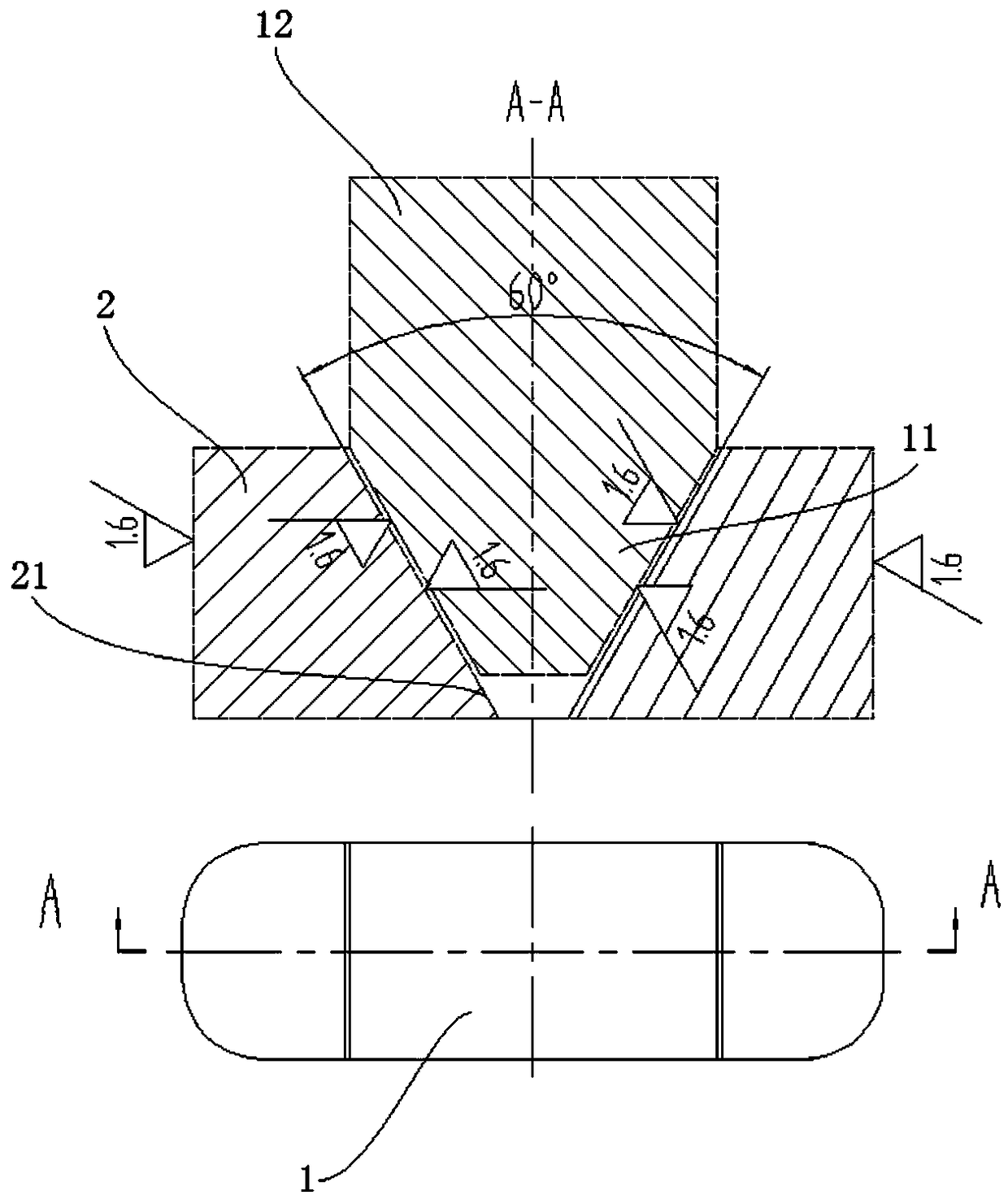
[0030] Such as Figures 1 to 4 As shown, a multifunctional calibration tool, the part to be calibrated is a thin-walled annular part, and the part to be calibrated is placed on a horizontal platform.

[0031] It is characterized in that it includes a pressing block 1, two expansion blocks 2 and a pressure unit.

[0032] The expansion block 2 is a right-angled trapezoidal cylinder. One end of the expansion block 2 has an inclined surface, which is marked as an inclined surface 21 . The two corners at the other end of the expansion block 2 are rounded. When the multifunctional calibration tool corrects the parts, the lower bottom of the two expansion blocks 2 is placed inside the part as a mirror image, and the slopes 21 of the two expansion blocks 2 are opposite to form a trapezoidal groove.

[0033] The pressing block 1 consists of a tip 11 and a rectangular cylinder 12 . The tip 11 is an isosceles trapezoidal cylinder. In this embodiment, the angle between the two slopes ...

Embodiment 2

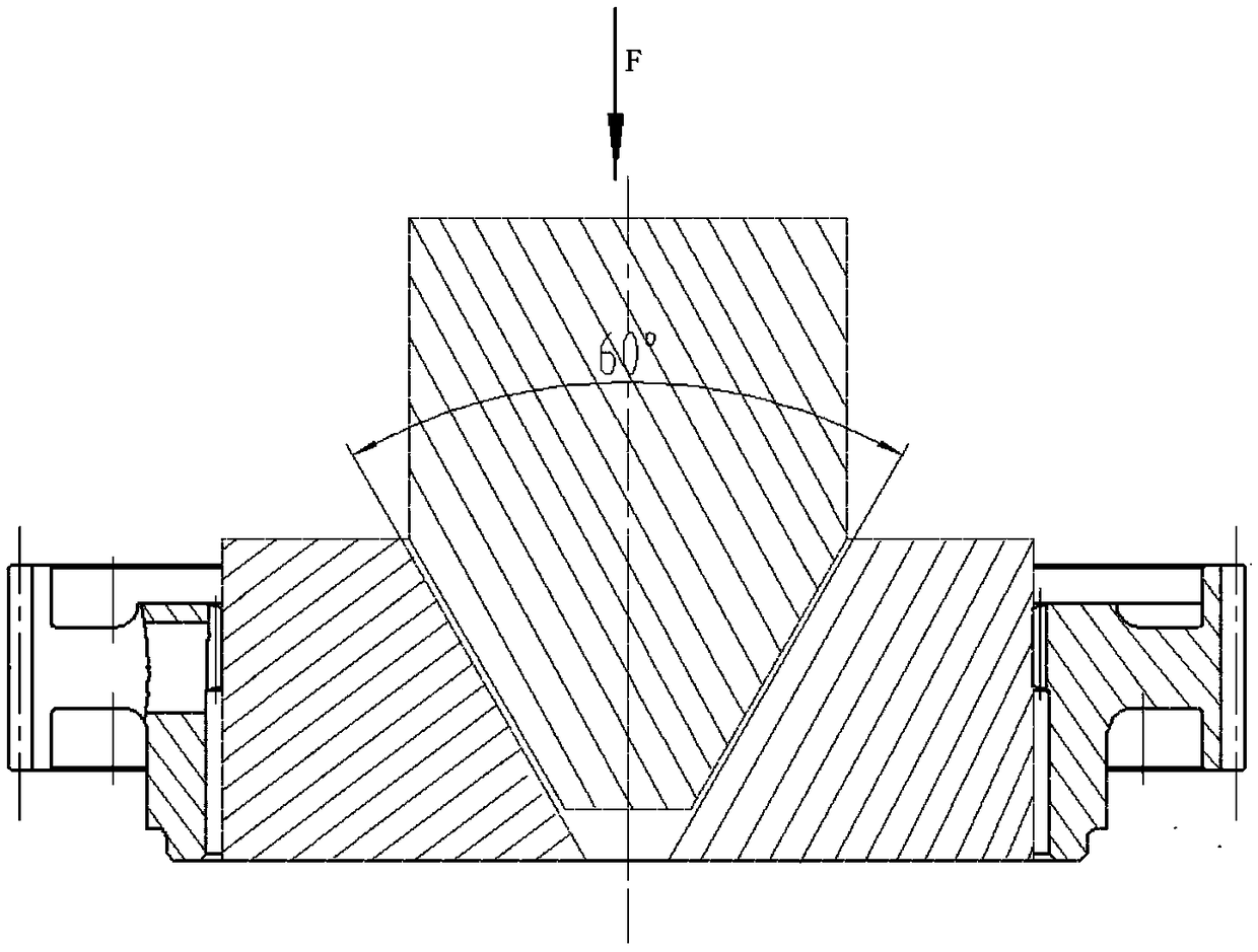
[0038] The structure of this embodiment is the same as that of Embodiment 1, and the operation process of the multifunctional calibration tool is further described. In this embodiment, the part to be corrected is the synchronizer cone. Refer to Figure 3 to Figure 4 ,Proceed as follows:

[0039] 1) Put the synchronizer cone on the horizontal platform, put the slopes 21 of the two expansion blocks 2 opposite, and put them into the synchronizer cone in a mirror image distribution.

[0040] 2) Insert the tip 11 of the pressing block 1 downward into the trapezoidal groove formed by the two expansion blocks 2 .

[0041] 3) Place the pressure unit on the top of the rectangular cylinder 12 of the briquetting block 1, and apply a force F perpendicular to the horizontal platform to the briquetting block 1.

[0042] 4) The pressing block 1 is forced and moves downward, and the tip 11 of the pressing block 1 applies force to the two expansion blocks 2, so that the two expansion blocks 2...


PUM


Abstract

The invention discloses a multifunctional correcting tool which comprises a compressing block, two expansion blocks and a pressure unit. The expansion blocks are right trapezoid shaped columns, one end is provided with an oblique surface and is regarded as an oblique plane, two edge corners at the other end are rounded corners, and when the multifunctional correcting tool corrects a part, the lower bottom surfaces of the two expansion blocks are downwards placed in the part in a mirror image way, the oblique planes of the two expansion blocks are opposite to form a trapezoid groove. The compressing block consists of a sharp end and a rectangular column, wherein the sharp end is an isosceles trapezoid column, the rectangular face of one end of the rectangular column coincides with the lowerbottom surface of the sharp end, and when the multifunctional correcting tool corrects the part, the sharp end of the compressing block is inserted into the trapezoid groove formed by the two expansion blocks and is matched with the trapezoid groove. The pressure unit acts on the top of the rectangular column of the compressing block and exerts a force perpendicular to a horizontal table top to the compressing block. The multifunctional correcting tool is wide in application range, low in manufacturing cost, long in service life and is conductive to ensuring of part quality and production progress.

Description

technical field [0001] The invention belongs to the field of tooling, and in particular relates to a multifunctional correction tooling. Background technique [0002] Due to the high precision requirements and high processing difficulty of thin-walled parts such as the synchronizer gear hub, synchronizer cone, synchronizer ring, sliding sleeve, and ring gear of the gearbox, the roundness pass rate of the parts manufactured by the existing processing technology is relatively low. Low, the roundness of some parts (about 10%) is out of tolerance after pressure quenching. However, such parts are not suitable for rework and repair, mainly because rework and repair are easy to cause problems such as oxidation and decarburization. There are external teeth in parts such as the synchronizer hub and the synchronizer cone, and the hardness of the parts is low after carburizing and air cooling. It is not possible to simply hit the top of the external teeth with a hammer during calibrati...

Claims


Application Information

Patent Timeline
Patent Type & Authority Applications(China)
IPC IPC(8): B21D3/14
Inventor 陈绍龙李富勇杨海龙刘海胡卫伍
Owner CHONGQING TIEMA IND GRP
Learn More