
Automatic feeding cutting device of frequency converter heat dissipating pipe

A technology of automatic feeding and cutting device, applied in the direction of positioning device, clamping, support, etc., can solve the problems of unusability, low degree of automation, waste, etc., and achieve the effect of accurate cutting length, improved production efficiency, and high degree of automation

Active Publication Date: 2019-01-18
CHAOHU JINHUI AUTOMATIC CONTROL EQUIP
View PDF8 Cites 0 Cited by
  • Summary
  • Abstract
  • Description
  • Claims
  • Application Information

AI Technical Summary

Problems solved by technology

This traditional method requires workers to manually position and fix the heat pipe to prevent the heat pipe from shifting, deflecting, etc. This method generally has problems such as low automation and inaccurate cutting lengths, which can easily cause the heat pipe to be damaged when it is in use. It also needs to be re-cut or the size of the cut heat pipe is unqualified and cannot be used, resulting in great waste

Method used


Image

  • Automatic feeding cutting device of frequency converter heat dissipating pipe
  • Automatic feeding cutting device of frequency converter heat dissipating pipe
  • Automatic feeding cutting device of frequency converter heat dissipating pipe

Examples


Embodiment Construction

[0028] The following will clearly and completely describe the technical solutions in the embodiments of the present invention with reference to the accompanying drawings in the embodiments of the present invention. Obviously, the described embodiments are only some, not all, embodiments of the present invention. Based on the embodiments of the present invention, all other embodiments obtained by persons of ordinary skill in the art without creative efforts fall within the protection scope of the present invention.

[0029] In describing the present invention, it is to be understood that the terms "opening", "upper", "lower", "thickness", "top", "middle", "length", "inner", "surrounding" etc. Indicating orientation or positional relationship is only for the convenience of describing the present invention and simplifying the description, and does not indicate or imply that the components or elements referred to must have a specific orientation, be constructed and operated in a sp...


PUM


Abstract

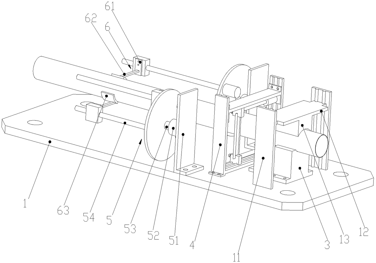
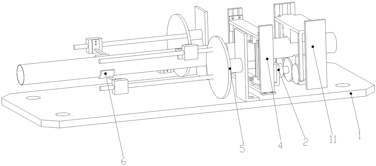
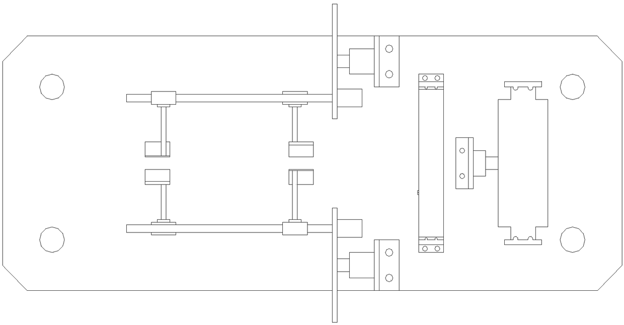
The invention discloses an automatic feeding cutting device of a frequency converter heat dissipating pipe. The device comprises a base, supporting frames are arranged on the base, a first supportingplatform is arranged between the supporting frames, a second supporting platform is arranged on the first supporting platform, a transmission rack is arranged at the lower end of the second supportingplatform, a driving unit is fixedly installed on the base, a placing platform is fixedly installed on the base, a cutting unit is fixedly installed on the base, a feeding unit is arranged on the upper end of the base, and a tight clamping unit is fixedly installed on the feeding unit. The feeding unit is started to tightly clamp the heat dissipating pipe, a rolling bead lead screw is driven to feed the heat dissipating pipe, when the feeding of the heat dissipating pipe is completed, the driving unit allows the second platform to tightly clamp the heat dissipating pipe placed on the placing platform, the cutting unit is started to cut the heat dissipating pipe, after the cutting of the first section of the heat dissipating pipe is completed, the heat dissipating pipe is expanded through the driving unit, a second rotary motor is started again to feed the heat dissipating pipe, and the next section of cutting of the heat dissipating pipe is conducted.

Description

technical field [0001] The invention relates to a cutting device, in particular to an automatic feeding cutting device for a frequency converter cooling pipe. Background technique [0002] The processing technology of the heat pipe generally includes raw material particle mixing, extrusion, mold forming, vacuum cooling and sizing, coding, cutting and so on. The cutting process is used to cut the heat pipe into the required length for different purposes. In the traditional cutting process, most of them are cut by manual pipe cutter, that is, the heat pipe to be cut is placed under the cutter of the manual pipe cutter. Hold the handle and apply downward pressure to allow the knife to cut through the heat pipe. This traditional method requires workers to manually position and fix the heat pipe to prevent the heat pipe from shifting, deflecting, etc. This method generally has problems such as low automation and inaccurate cutting lengths, which can easily cause the heat pipe to...

Claims


Application Information

Patent Timeline
Patent Type & Authority Applications(China)
IPC IPC(8): B23Q3/06B23Q7/00
CPCB23Q3/06B23Q3/062B23Q3/064B23Q7/00
Inventor 何来传
Owner CHAOHU JINHUI AUTOMATIC CONTROL EQUIP
Learn More