
High-pressure nitrogen balance weight balance cylinder system for workpiece machining

A technology of high-pressure nitrogen and counterweight balance, which is applied in metal processing equipment, metal processing machinery parts, manufacturing tools, etc., can solve the problems of non-responsiveness, improve surface finish, reduce forward and reverse buffering, and move smoothly Effect

Inactive Publication Date: 2019-01-18
安徽恒辉机械有限公司
View PDF7 Cites 4 Cited by
  • Summary
  • Abstract
  • Description
  • Claims
  • Application Information

AI Technical Summary

Problems solved by technology

[0004] In order to overcome the above-mentioned technical problems, the object of the present invention is to provide a high-pressure nitrogen counterweight balance cylinder system for workpiece processing, which can solve the problem that the traditional gas counterweight balance cylinder system does not have a sensitive response when moving up and down the Z axis, reducing Forward and reverse buffering can effectively improve the surface finish of workpiece processing, and can also increase the moving speed

Method used


Image

  • High-pressure nitrogen balance weight balance cylinder system for workpiece machining
  • High-pressure nitrogen balance weight balance cylinder system for workpiece machining
  • High-pressure nitrogen balance weight balance cylinder system for workpiece machining

Examples


Embodiment Construction

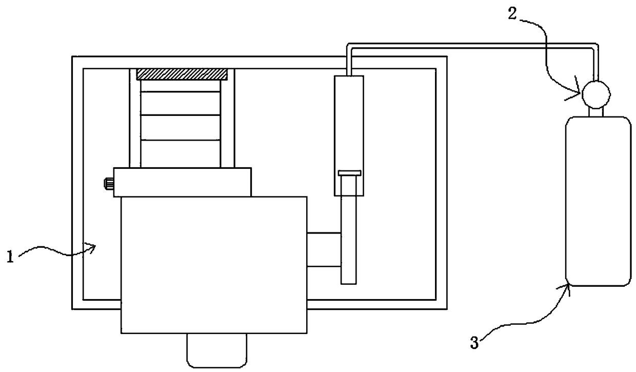
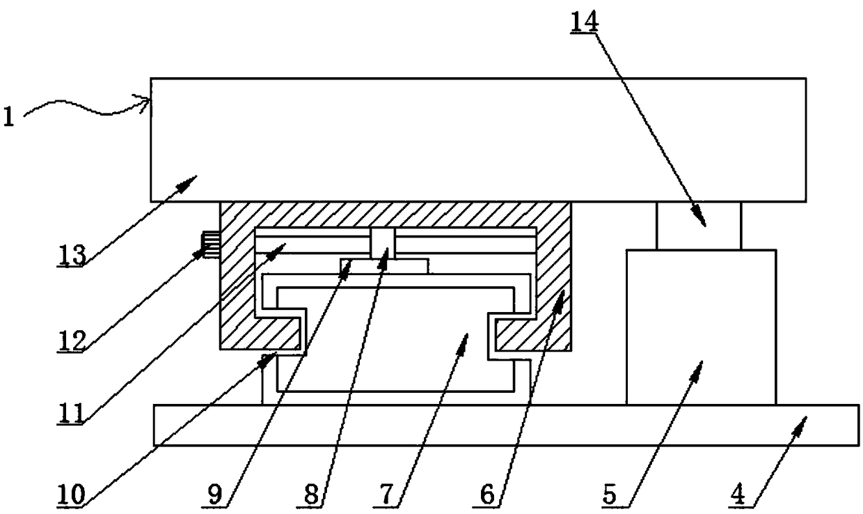
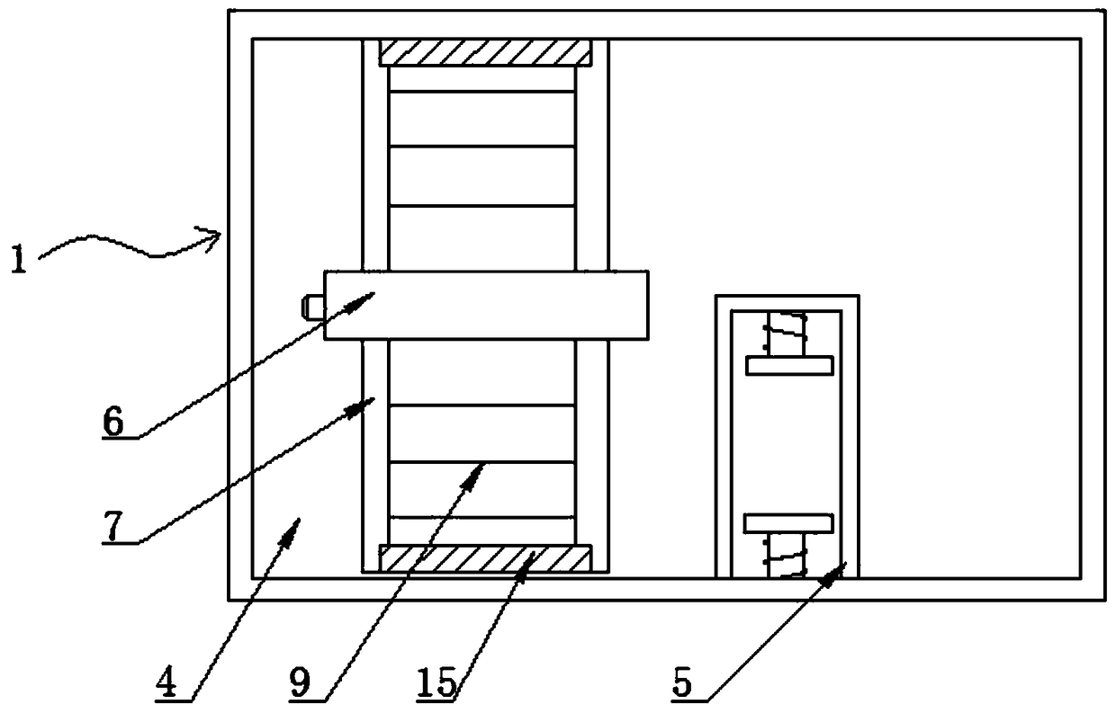
[0028] The technical solutions in the embodiments of the present invention will be clearly and completely described below in conjunction with the embodiments of the present invention. Apparently, the described embodiments are only some of the embodiments of the present invention, not all of them. Based on the embodiments of the present invention, all other embodiments obtained by persons of ordinary skill in the art without creative efforts fall within the protection scope of the present invention.

[0029] see Figure 1-4 As shown, a high-pressure nitrogen balance cylinder system for workpiece processing includes a nitrogen balance member 1, a controller 2 and a nitrogen tank 3, and the nitrogen balance member 1 includes a fixed plate 4, a sliding member 5, and a first slider 6 , the first slide rail 7, the gear 8, the rack 9, the chute 10, the rotating shaft 11, the servo motor 12, the spindle box 13, the second slider 14, the limit block 15, the cylinder body 16, the cylind...


PUM


Abstract

The invention discloses a high-pressure nitrogen balance weight balance cylinder system for workpiece machining. The high-pressure nitrogen balance weight balance cylinder system comprises a nitrogenbalance component, a controller and a nitrogen container. One side of a fixed plate is fixedly connected with a first sliding rail, a gear rack is arranged at the top of the first sliding rail, one side of the first sliding block is fixedly connected with a servo motor, and an output shaft of the servo motor is fixedly connected with one end of a rotary shaft arranged on the hollow portion of thefirst sliding block. The other end of the rotary shaft is rotationally connected with one side of the inner wall of the first sliding block, the middle of the rotary shaft is connected with a gear through a connecting key, the bottom of the first sliding block is fixedly connected with a spindle box, and one side of the spindle box is connected with an air cylinder piston rod, stretching outwards,on an air cylinder body through a connecting block. According to the high-pressure nitrogen balance weight balance cylinder system, the problems that a traditional air balance weight balance cylindersystem does not have the advantages of being sensitive in response during vertical movement of an axis Z, reducing forward and reverse buffering, effectively improving the surface smoothness of workpiece machining and being capable of increasing the movement speed are solved.

Description

technical field [0001] The invention relates to the technical field of gas balance cylinder systems, in particular to a high-pressure nitrogen balance cylinder system for workpiece processing. Background technique [0002] A machine tool such as a machining center is provided with a main shaft and a main shaft assembly having an electric motor for rotationally driving the main shaft, and the main shaft assembly is supported and driven up and down by an elevating drive mechanism. This lifting drive mechanism is usually a ball screw, a ball nut screwed with the ball screw and connected to the main shaft assembly, and an electric motor, and the main shaft assembly and the ball nut are driven up and down together by the electric motor rotating the ball screw. . [0003] Since the lifting drive mechanism is mainly driven by the motor, the load of the lifting drive mechanism is very large, which may reduce the position accuracy of the spindle assembly in the vertical direction, a...

Claims


Application Information

Patent Timeline
IPC IPC(8): B23Q11/00
CPCB23Q11/0025
Inventor 周银桂盛鹏
Owner 安徽恒辉机械有限公司
Learn More