A hole-making method for ion propulsion carbon grid assembly

A technology of ion propulsion and components, which is applied in metal processing and other directions, can solve the problems such as the inability to apply carbon grid porous manufacturing applications, the inability to apply spherical crown carbon grid component processing, and the large measurement error of spherical crown shape workpieces, etc., to achieve the suppression of burrs And delamination defects, improve the rigidity, good effect of precision consistency

Active Publication Date: 2020-01-24
DALIAN UNIV OF TECH
View PDF5 Cites 1 Cited by
  • Summary
  • Abstract
  • Description
  • Claims
  • Application Information

AI Technical Summary

Problems solved by technology

[0004] In 2014, Qin Xuda and others in the invention patent CN104289738B "Laminated structure hole making online monitoring adaptive processing method," measured the distance between the bottom of the hole making tool and the material interface by ultrasonic thickness measurement, and controlled the tool through feedback. Processing parameters, but ultrasonic measurement has a large measurement error for spherical crown-shaped workpieces, which cannot be applied to the processing of spherical crown-shaped carbon grid components; In the hole-making device and method", liquid nitrogen is used as the cooling medium for temperature closed-loop control, so that the temperature of the processing area is between -60°C and -40°C, and the low-temperature medium is effectively used to reduce the cutting temperature and maintain the sharpness of the tool. Due to the limitations of the temperature sensor device, the method cannot be applied to the manufacturing application of porous carbon grids

Method used


Image

  • A hole-making method for ion propulsion carbon grid assembly
  • A hole-making method for ion propulsion carbon grid assembly

Examples


Embodiment Construction

[0017] Embodiments of the present invention will be described in detail in conjunction with the accompanying drawings.

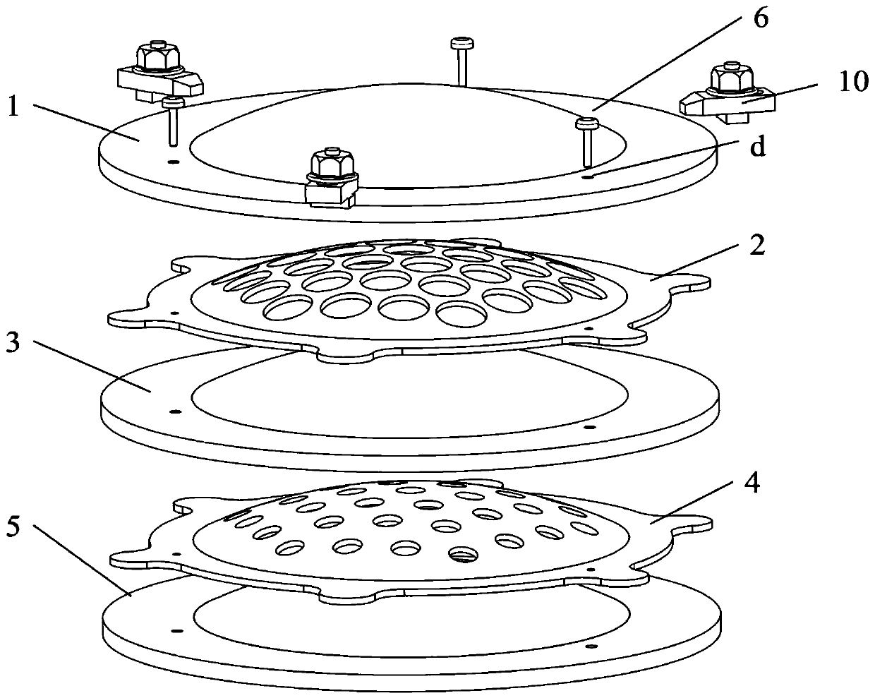
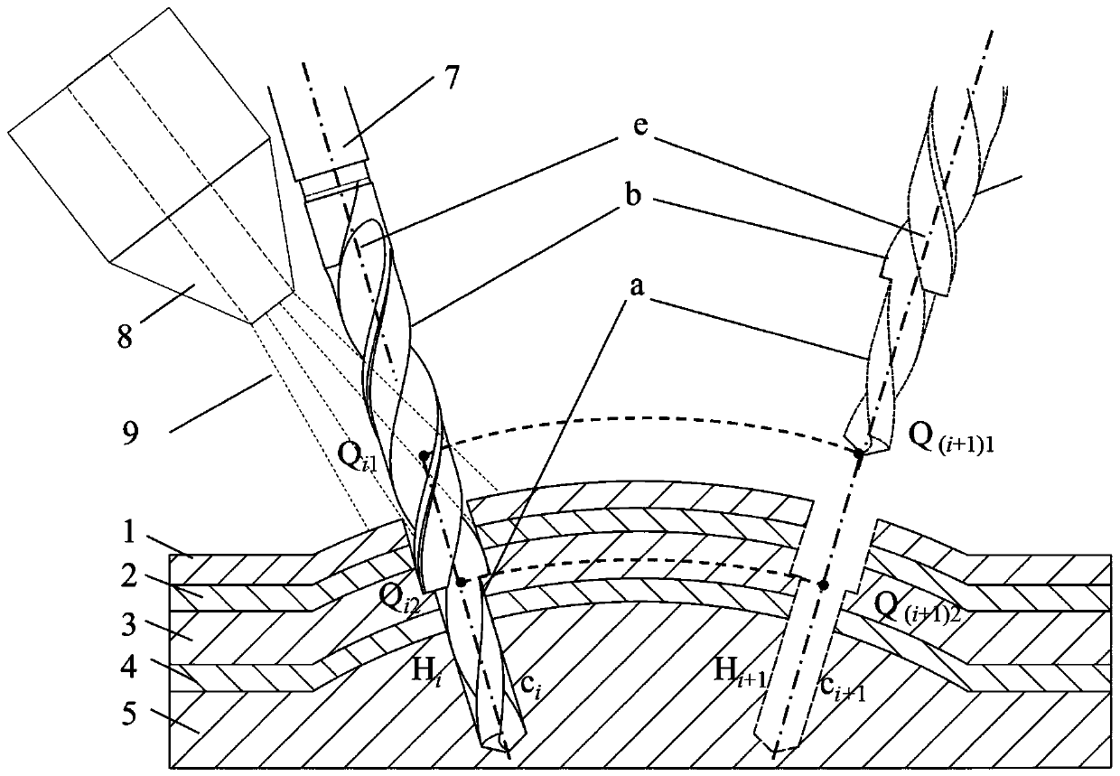
[0018] figure 1 It is a schematic diagram of the positioning and clamping of the carbon grid assembly. In this embodiment, the screen grid 2 has a diameter of 110 mm and a thickness of 0.5 mm, and the acceleration grid 4 has a diameter of 110 mm and a thickness of 0.7 mm. The diameter of the front end of the stepped drill bit 7 is 1.1 mm, and the diameter of the rear end is 1.9 mm.

[0019] The specific steps of the method are as follows:

[0020] The first step is "sandwich" clamping

[0021] The spherical crown-shaped carbon grid assembly is composed of screen grid 2 and acceleration grid 4; the surface shape of the aluminum alloy backing plate is consistent with the surface shape of the matching surface of the corresponding grid; the aluminum alloy lower backing plate 5, the acceleration grid 4, The aluminum alloy intermediate backing plate 3, the scre...


PUM


Abstract

The invention provides a drilling method for a carbon grid assembly of an iron propeller, belongs to the field of iron propeller manufacturing, and relates to a mechanical processing method of pairs of drill holes of the carbon grid assembly under one-time clamping by utilizing a mode for cooling drill holes through a step drill and external sprayed high-pressure liquid nitrogen. The method comprises the steps that firstly, the spherical-crown-shaped carbon grid assembly is clamped on a machine table in a 'sandwich' mode, the step drill is used for different diameters of small holes in pairs of the carbon grid assembly at a time, and the high-pressure liquid nitrogen is used for cooling processing to reduce the cutting temperature; then, drilling of other carbon grid array holes is completed under the control of a numerical control system. The method effectively reduces burrs and lamination defects which are caused by drilling by adding upper and lower supporting plates of the carbon grid assembly, the liquid nitrogen is used for cooling processing to greatly reduce the temperature of a cutting area, and oxidation, ablation and other defects of the carbon grid assembly are effectively restrained; the position precision of the array holes of the carbon grid assembly is ensured by using the step drill to process the holes in pairs at a time, the processing efficiency is high, andthe precision uniformity is good.

Description

technical field [0001] The invention belongs to the field of ion thruster manufacturing, and relates to a method for making holes in a carbon grid assembly of an ion thruster, which realizes a machining method for drilling holes in pairs of the carbon grid assembly in one clamping. Background technique [0002] The grid assembly is the key functional part of the ion thruster. It is composed of a screen grid and an acceleration grid in pairs. Thousands of small holes with extremely strict shape and position accuracy are designed on it, and the small holes of the two grids are designed in pairs, that is, The axes of the paired holes coincide. Under the action of a strong electric field, the accelerated ion flow is ejected at high speed from the small holes in the grid assembly array, forming a thrust. If there is a deviation in the aperture and axis posture of the paired small holes of the grid assembly, it will inevitably affect the thrust stability and accelerate the grid l...

Claims


Application Information

Patent Timeline
Patent Type & Authority Patents(China)
IPC IPC(8): B26F1/16B26D7/02B26D7/08
CPCB26D7/02B26D7/08B26F1/16
Inventor 刘海波王晋宇韩灵生仲小清甘涌泉刘阔王永青郭东明
Owner DALIAN UNIV OF TECH
Why Eureka
Try Eureka