Silt removal device for channel improvement

A technology of river remediation and removal device, applied in the direction of earth mover/shovel, mechanically driven excavator/dredger, construction, etc., can solve the problem of difficult to completely remove stubborn silt, long silt accumulation time, easy to fall again and other problems, to achieve the effect of reducing the burden on the hull, reducing the weight and reducing the resistance

Inactive Publication Date: 2019-01-18
盐城恒清河湖整治有限公司
View PDF0 Cites 10 Cited by
  • Summary
  • Abstract
  • Description
  • Claims
  • Application Information

AI Technical Summary

Problems solved by technology

[0002] As we all know, the silt removal device for river channel regulation is a device used to clean the bottom of the river channel, remove the accumulated silt, and maintain the river channel environment during the process of river channel maintenance and improvement. Good use value can better improve the river environment, and it is widely used in the field of dredging; the existing sludge removal device for river regulation includes a hull, the bottom of the hull is provided with a working chamber, and the top of the hull is provided with a control room ; This kind of silt removal device for river channel regulation drives the hull to the working place when it is in use, and uses the mechanical arm on the hull to drive the grabbing shovel to scrape and grab the silt at the bottom of the river channel, and then put the silt to the designated position; During the use of this kind of silt removal device for river channel improvement, it was found that the silt picked up by the grab shovel has not been dehydrated, and it is easier to fall back into the river channel. The silt accumulation takes a long time, and it is difficult to completely remove the stubborn silt with the grab shovel, and the sludge treatment is relatively simple. , causing certain impact and damage to the environment during the disposal process

Method used


Image

  • Silt removal device for channel improvement
  • Silt removal device for channel improvement
  • Silt removal device for channel improvement

Examples


Embodiment Construction

[0017] The specific implementation manners of the present invention will be further described in detail below in conjunction with the accompanying drawings and embodiments. The following examples are used to illustrate the present invention, but are not intended to limit the scope of the present invention.

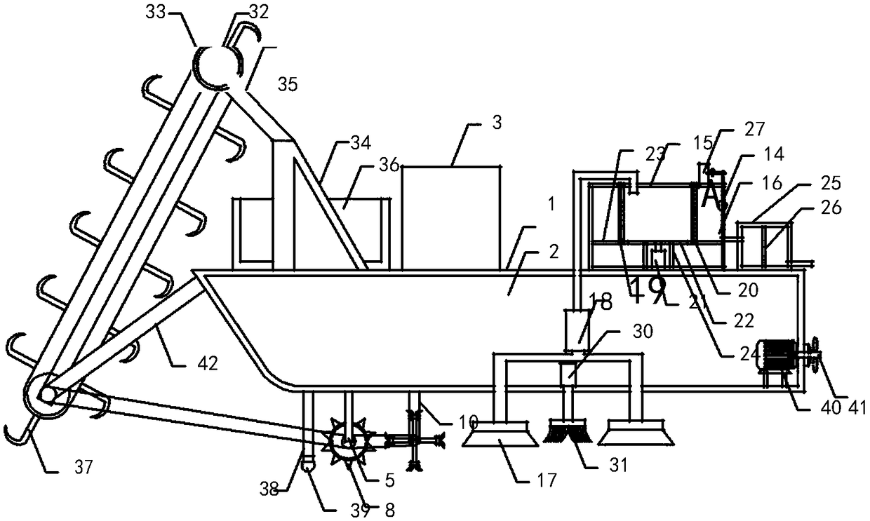
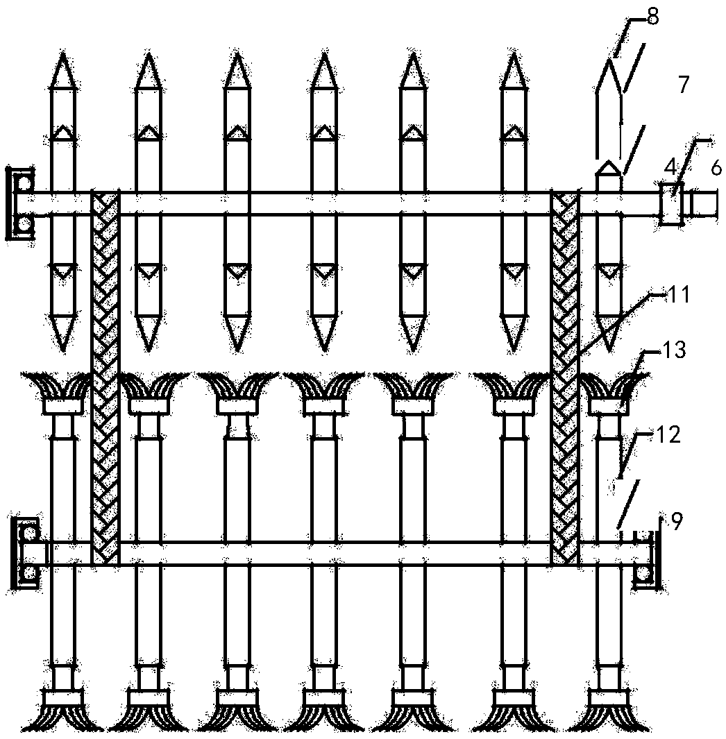
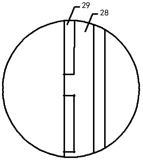
[0018] Such as Figure 1 to Figure 3As shown, a kind of silt removal device for river regulation of the present invention comprises a hull 1, a working chamber 2 is arranged at the bottom of the hull 1, and a control room 3 is arranged at the top of the hull 1; it also includes a first rotating shaft 4, a first connecting rod 5, The second connecting rod and the submersible motor 6, the first connecting rod 5 and the second connecting rod are all arranged at the bottom of the hull 1, the top of the first connecting rod 5 is connected with the bottom of the hull 1, and the bottom of the first connecting rod 5 is connected with the submersible motor 6 shell connection, the ...


PUM


Abstract

The invention relates to the technical field of channel improvement, in particular to a silt removal device for channel improvement. The silt removal device for channel improvement can stir stubborn silt more thoroughly, improve the treatment degree of salvaged silt, better dehydrate the silt, reduce the influence on and damage to the environment, improve the use reliability of the device and improve the degree of automation. The silt removal device for the channel improvement comprises a hull, wherein the bottom of the hull is provided with a working cavity, and the top end of the hull is provided with a control chamber; the silt removal device further comprises a first rotating shaft, a first connecting rod, a second connecting rod and a submersible motor, the first connecting rod is provided with multiple sets of rolling wheel groups, and the multiple sets of rolling wheel groups are evenly provided with stirring teeth; the silt removal device further comprises a second rotating shaft, a third connecting rod, a fourth connecting rod, a conveyor belt group, a first connecting pipe, a second connecting pipe, a silt box and a dehydration cylinder, the dehydration cylinder is internally provided with a dehydration cavity, and a water placement cavity is formed between the inner wall of the silt box and the outer wall of the dehydration cylinder.

Description

technical field [0001] The invention relates to the technical field of river regulation, in particular to a silt removal device for river regulation. Background technique [0002] As we all know, the silt removal device for river channel regulation is a device used to clean the bottom of the river channel, remove the accumulated silt, and maintain the river channel environment during the process of river channel maintenance and improvement. Good use value can better improve the river environment, and it is widely used in the field of dredging; the existing sludge removal device for river regulation includes a hull, the bottom of the hull is provided with a working chamber, and the top of the hull is provided with a control room ; This kind of silt removal device for river channel regulation drives the hull to the working place when it is in use, and uses the mechanical arm on the hull to drive the grabbing shovel to scrape and grab the silt at the bottom of the river channel...

Claims


Application Information

Patent Timeline
IPC IPC(8): E02F3/88E02F5/28
CPCE02F3/885E02F5/28
Inventor 刘汝群
Owner 盐城恒清河湖整治有限公司
Why Eureka
Try Eureka