Melting furnace for rock wool production

A technology for melting furnaces and rock wool, applied in furnaces, furnace components, furnace types, etc., can solve the problems of non-compliance with energy saving and environmental protection, low production efficiency, waste of water and heat energy, etc., to ensure continuous production operation, improve production efficiency, improve The effect of the overall benefit

Pending Publication Date: 2019-01-18
郁平
View PDF0 Cites 0 Cited by
  • Summary
  • Abstract
  • Description
  • Claims
  • Application Information

AI Technical Summary

Problems solved by technology

With the development of the national economy and the implementation of the national energy-saving policy, the demand for rock and mineral wool products for building and industrial thermal insulation is increasing. However, the existing domestic cupolas for the production of rock and mineral wool are generally traditional Jacketed shaft furnace, the cooling water is passed into the middle jacket, the temperature of the cooling water rises after passing through the melting furnace, and it is cooled by the cooling tower. After cooling, the water is passed into the jacket of the melting furnace to cool the furnace wall Cool down to ensure that the furnace wall will not be melted and deformed. In this way, water heat energy is wasted during the water circulation process. At the same time, a large amount of electric energy is used to drive the motor for blowing and water pump circulation, resulting in 80% energy waste, which does not meet the needs of energy conservation and environmental protection.
In addition, most of the existing melting furnaces are artificially and actively fed according to the combustion of raw materials, and the production efficiency is low

Method used


Image

  • Melting furnace for rock wool production
  • Melting furnace for rock wool production
  • Melting furnace for rock wool production

Examples


Embodiment Construction

[0015] In order to make those skilled in the art understand the present invention better, the present invention will be further described below in conjunction with specific embodiment:

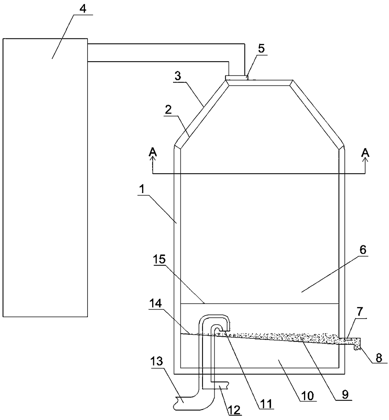
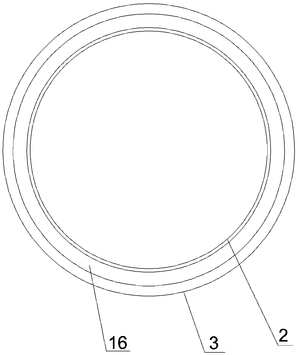
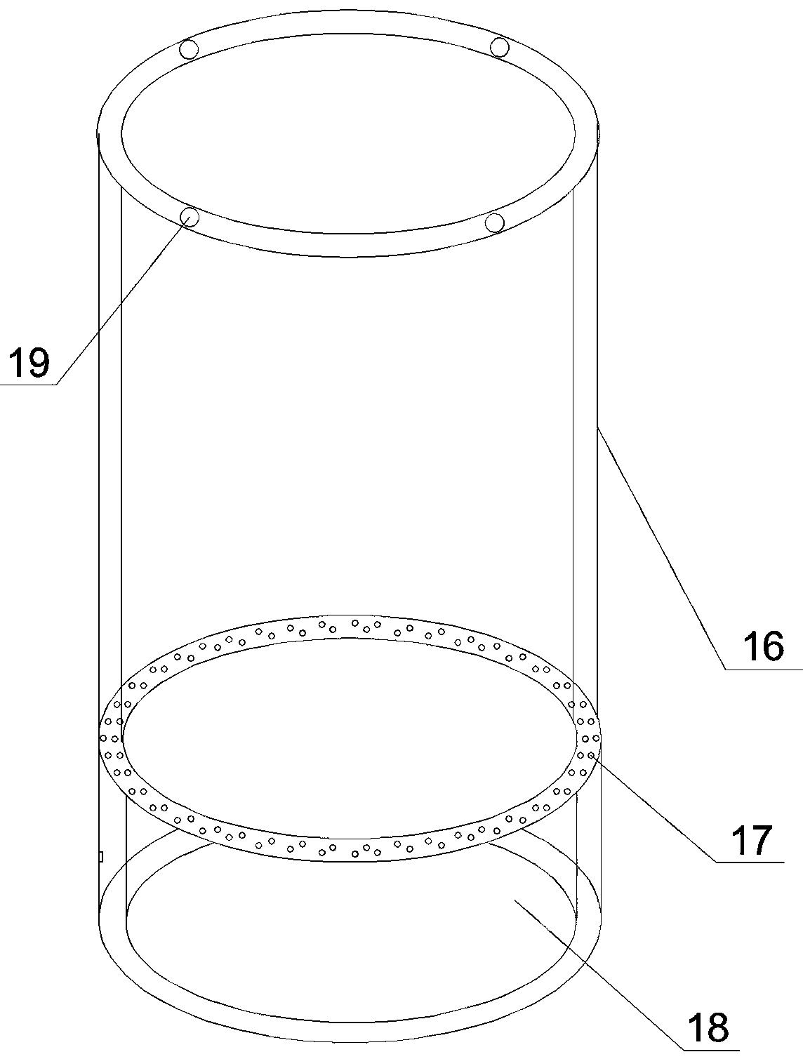
[0016] like Figure 1 to Figure 3 As shown, a melting furnace for rock wool production includes a melting furnace body 1, the melting furnace body 1 is a cylindrical structure, the furnace wall of the melting furnace includes an inner wall 2 and an outer wall 3, and between the inner wall 2 and the outer wall 3 An annular channel 16 parallel to the direction of the melting furnace cylinder is provided. An annular water tank 18 is provided at the bottom of the annular channel 16. The annular water tank 18 surrounds the lower part of the melting furnace. The top of the annular water tank 18 is provided with a through hole 17. The annular channel 16 It communicates with the annular water tank 18 through the through hole 17; the bottom side of the annular water tank 18 is provided with a water inl...


PUM


Abstract

The invention discloses a melting furnace for rock wool production. The furnace includes a cylindrical melting furnace body, the wall of the melting furnace includes an inner wall body and an outer wall body, an annular channel is formed between the inner wall body and the outer wall body, the bottom of the annular channel is provided with an annular water tank, and the annular channel is communicated with the annular water tank through a through hole; the top of the melting furnace is provided with a feeding hole which is connected with a feeding system; the side face of the melting furnace is provided with a discharge hole, a liquid level meter is arranged at the discharge hole, an air inlet is arranged on the bottom of the melting furnace, and the air inlet is connected with an air intake system; the feeding system, the liquid level meter and the air intake system are electrically connected with a control system. The air intake system, the feeding system, the liquid level meter areconnected with the control system, feeding and air intake of the combustion furnace can be automatically controlled according to the combustion situation of materials in a combustion furnace and the discharge situation of the discharge hole, the continuous production operation of the combustion furnace is effectively ensured, the production efficiency is improved, the cost is saved and the overallbenefit of the rock wool production is improved.

Description

technical field [0001] The invention relates to the technical field of rock wool production equipment, in particular to a melting furnace for rock wool production. Background technique [0002] Rock wool is a common thermal insulation material. Raw materials such as basalt, coke, dolomite and slag are melted, centrifuged to make them fibrous, and then further processed to form rock wool boards or other products. With the development of the national economy and the implementation of the national energy-saving policy, the demand for rock and mineral wool products for building and industrial thermal insulation is increasing. However, the existing domestic cupolas for the production of rock and mineral wool are generally traditional Jacketed shaft furnace, the cooling water is passed into the middle jacket, the temperature of the cooling water rises after passing through the melting furnace, and it is cooled by the cooling tower. After cooling, the water is passed into the jacke...

Claims


Application Information

Patent Timeline
Patent Type & Authority Applications(China)
IPC IPC(8): F27B17/00F27D17/00
CPCF27B17/00F27D17/004Y02P10/25
Inventor 郁平
Owner 郁平
Why Eureka
Try Eureka