Eureka AIR delivers breakthrough ideas for toughest innovation challenges, trusted by R&D personnel around the world.

A sucker type electromagnet sealed magnetic conduction structure

An electromagnet and sucker-type technology, applied in the field of deep sea detection, can solve the problems of different forms of electromagnets, and achieve the effects of short supply cycle, easy installation and replacement, and reliable sealing.

Active Publication Date: 2020-11-20
HARBIN ENG UNIV
View PDF10 Cites 1 Cited by
  • Summary
  • Abstract
  • Description
  • Claims
  • Application Information

AI Technical Summary

Problems solved by technology

The electromagnetic driving method is one of the commonly used driving methods in ballast release devices, but the existing electromagnets have no finished products suitable for deep sea environments, so the electromagnet seals the magnetic structure so that the electromagnetic driving method can still be used in deep seas
[0003] The existing electromagnet sealing structure, such as the electromagnet structure designed by the patent document named "Special Electromagnet for Underwater Separation System" with the patent No. The electromagnet sealing structure designed in the patent document, the electromagnet sealing structure designed in the patent document with the patent number 201720958994.7 titled "Electromagnet sealing structure and wading robot", etc., can complete the basic watertightness of the electromagnet, but the form of the electromagnet is different , the use environment is also shallow water and low pressure environment, and cannot work in deep sea and high external pressure environment

Method used


Image

  • A sucker type electromagnet sealed magnetic conduction structure
  • A sucker type electromagnet sealed magnetic conduction structure
  • A sucker type electromagnet sealed magnetic conduction structure

Examples


Embodiment Construction

[0017] Below in conjunction with accompanying drawing, the patent of the present invention is described in further detail.

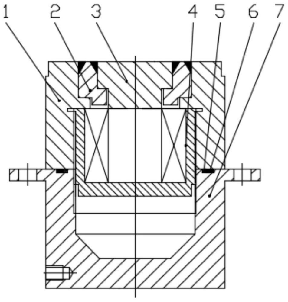
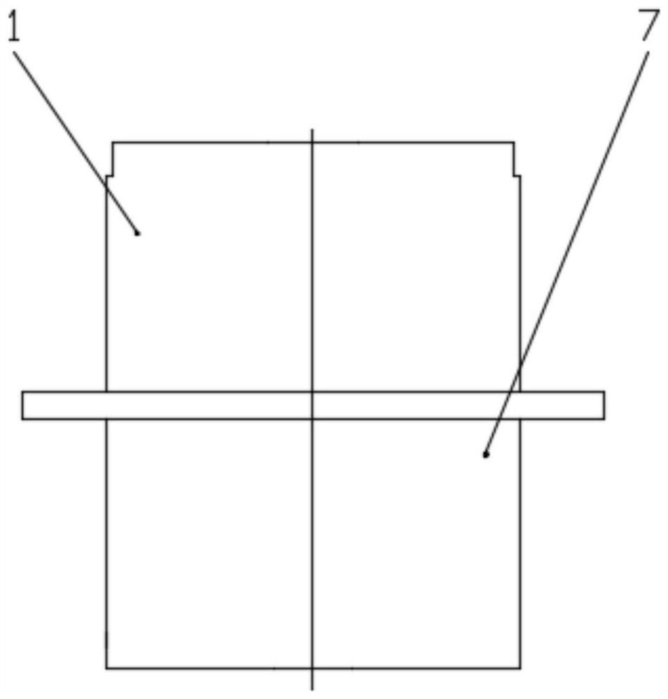
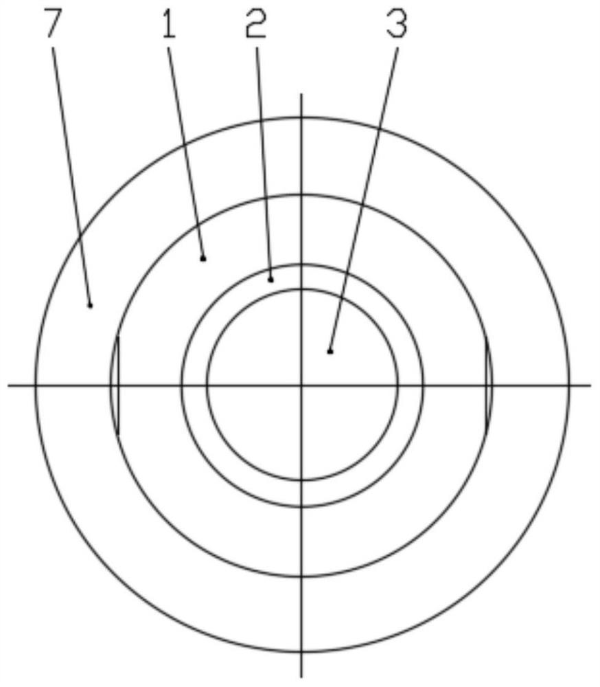
[0018] The patent of the present invention relates to a sucker-type electromagnet sealed magnetic conduction structure, which is mainly composed of four parts: an upper cover 1, a magnetic conduction cylinder 3, a pressure bearing part 2, and a lower cover 7. The magnetically conductive cylinder 3 and the upper cover 1 are made of magnetically conductive material, the pressure bearing part 2 and the lower cover 7 are made of nonmagnetically conductive material; one end of the magnetically conductive cylinder 3 is in close contact with the magnetic core of the electromagnet 4, and the upper cover 1 is in contact with the shell of the electromagnet 4 , When the electromagnet 4 is in the working state, the attracted object forms a closed magnetic circuit with the upper cover 1, the shell of the electromagnet 4, the magnetic core and the magnetic conduction c...


PUM


Abstract

The invention belongs to the field of deep-sea exploration, in particular to a suction disk-type electromagnet sealing magnetic conductivity structure. The structure comprises an upper cover, a pressure-bearing member, a magnetic conductive cylinder, an electromagnet, a retaining ring, an O-ring, a lower cover; a magnetic conductive cylinder and an upper cover are magnetic conductive materials, and the pressure-bearing member and the lower cover are non-magnetic conductive materials. one end of that magnetically conductive cylinder is in close contact with the magnet core of the electromagnet,the upper cover is in contact with the electromagnet housing, and when the electromagnet is in the work state, the attracted object forms a closed magnetic circuit with the upper cover, the electromagnet housing, the magnet core and the magnetically conductive cylinder. The structure can not only seal the electromagnet, but also lead the magnetic force of the electromagnet out, and is especiallysuitable for the equipment needing the electromagnet in the deep sea environment. As that electromagnet of the invention is selecte from the common suction disk electromagnet, no additional customization is required, therefore, the supply period is short, the cost is low, the replacement is easy, the seal is reliable, the structure is an independent module, the installation and replacement are convenient, the shell wall thickness is designed according to different working depths, sufficient space is provide, and unnecessary weight is reduced.

Description

technical field [0001] The invention belongs to the field of deep-sea detection, and in particular relates to a sucker type electromagnet sealed magnetic conduction structure. Background technique [0002] Underwater operating equipment such as autonomous underwater robots work in a complex marine environment, not only threatened by the surrounding environment, but also may malfunction due to various emergencies. When the autonomous underwater robot diagnoses a limit fault or its fault-tolerant control strategy fails, abandoning the operation task and throwing the load to float is the only way for the autonomous underwater robot to save itself. Therefore, the ballast release device is a necessary equipment in the safety guarantee system of underwater operating equipment such as autonomous underwater robots. The electromagnetic driving method is one of the commonly used driving methods in ballast release devices, but there is no finished product suitable for deep sea environ...

Claims


Application Information

Patent Timeline
Patent Type & Authority Patents(China)
IPC IPC(8): H01F7/06
CPCH01F7/06
Inventor 张铭钧陈泽宇鲍林赵文德王玉甲屈建飞吕涛
Owner HARBIN ENG UNIV
Why Eureka
Eureka Blog
Learn More