High-power thermally superconducting plate-fin combined radiator

A thermal superconducting, combined technology, applied in the direction of semiconductor devices, semiconductor/solid-state device components, electric solid-state devices, etc., can solve problems such as the inability to meet the heat dissipation of high-power devices, and achieve weight and thickness reduction, cost reduction, and strength. improved effect

Pending Publication Date: 2019-01-18
ZHEJIANG JIAXI TECH CO LTD
View PDF0 Cites 2 Cited by
  • Summary
  • Abstract
  • Description
  • Claims
  • Application Information

AI Technical Summary

Problems solved by technology

[0003] In view of the shortcomings of the prior art described above, the purpose of the present invention is to provide a high-power thermal superconducting plate-fin combined heat sink, which is used to solve the problem that the heat sink in the prior art cannot meet the heat dissipation requirements of high-power devices

Method used


Image

  • High-power thermally superconducting plate-fin combined radiator
  • High-power thermally superconducting plate-fin combined radiator
  • High-power thermally superconducting plate-fin combined radiator

Examples


Embodiment 1

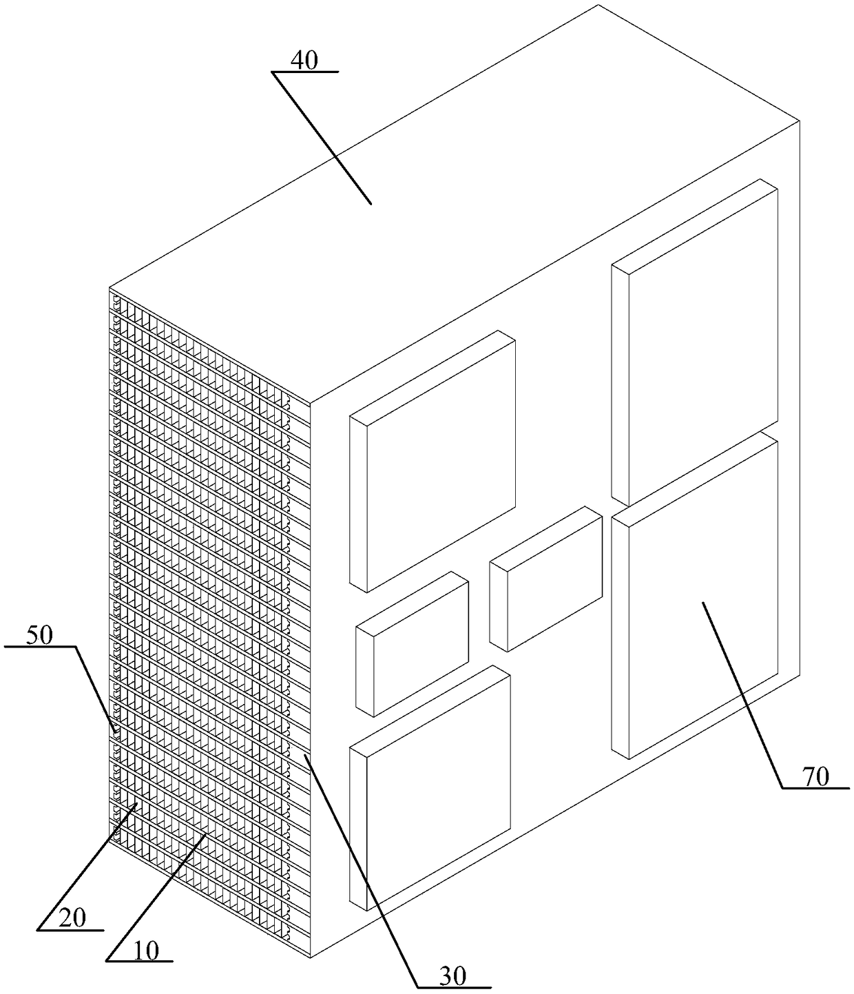
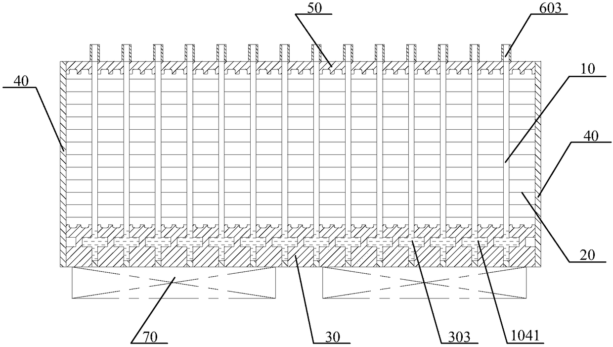
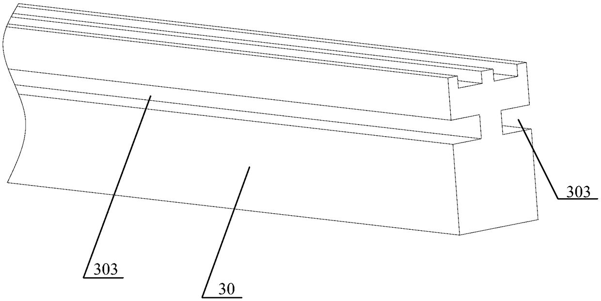
[0084] see Figure 1 to Figure 2 , the present invention provides a high-power thermal superconducting plate-fin combined radiator, the high-power thermal superconducting plate-fin combined radiator includes: several thermal superconducting plates 10 arranged at intervals, the thermal superconducting plates 10 is formed with interconnected heat transfer channels (not shown), the heat transfer channels are filled with heat transfer working fluid 1041; several bottom substrate spacers 30, the bottom substrate spacers 30 are located adjacent to the Between the thermal superconducting plates 10, and attached to the surface of the thermal superconducting plate 10; at least one side of the bottom substrate spacer 30 is provided with a groove 303 on the surface that is in contact with the thermal superconducting plate 10; The surface of the thermal superconducting plate 10 in contact with the bottom substrate spacer 30 is provided with a connection through hole 105 connecting the hea...

Embodiment 2

[0115] Please combine Figure 1 to Figure 20 refer to Figure 21 to Figure 25 , this embodiment also provides a high-power thermal superconducting plate-fin combined heat sink, the structure of the high-power thermal superconducting plate-fin combined heat sink described in this embodiment is the same as the high-power The structure of the thermal superconducting plate-fin combined radiator is roughly the same, and the difference between the two is that the high-power thermal superconducting plate-fin combined radiator described in this embodiment is compared with the high-power thermal superconducting radiator described in the first embodiment. A top connecting plate 60 is added to the thermal superconducting plate-fin combined radiator, and the top connecting plate 60 is located above the top substrate spacer 50 and the thermal superconducting plate 10; the extension direction of the top connecting plate 60 It is perpendicular to the surface of the thermal superconducting p...

Embodiment 3

[0118] Please combine Figure 1 to Figure 25 refer to Figure 26 to Figure 28, this embodiment also provides a high-power thermal superconducting plate-fin combined radiator, the structure of the high-power thermal superconducting plate-fin combined radiator described in this embodiment is the same as the high-power The structure of the thermal superconducting plate-fin combined radiator is roughly the same, the difference between the two is that the specific structure of the top connecting plate 60 is different, specifically: the top connecting plate 60 in the second embodiment is formed with a filling groove 60 and the filling hole 602 connected with the filling groove 601, the filling groove 601 extends along the length direction of the top communicating plate 60, and is connected with the conduction in each thermal superconducting plate 10 The heat passages are all connected, that is, the top communication plate 60 in the second embodiment is formed with a filling groove ...


PUM


Abstract

A high-power thermally superconducting plate-fin combined radiator is composed of several spaced thermally superconducting plates with intercommunicating heat transfer channels filled with heat transfer working medium. A plurality of bottom substrate spacers are positioned between adjacent thermal superconducting plates and attached to the surface of the thermal superconducting plate; At least oneside of that space strip of the bottom substrate is provided with a groove on the surface contacting with the thermal superconducting plate; The surface of the thermally superconducting plate contacting with the partition strip of the bottom substrate is provided with a connecting through hole for communicating the heat transfer channel with the channel. The heat dissipation fin is located on atleast one surface of the thermal superconducting plate and above the bottom substrate spacer. The grooves on the two sides of the base plate spacer strip in the high-power thermally superconducting plate-fin combined radiator of the invention can be used as buffer and storage areas of the heat transfer working substance, balance the distribution of the heat transfer working substance, play the role of communication or isolation between the thermally superconducting plates, and also play the role of increasing the heating area of the heat transfer working substance.

Description

technical field [0001] The invention belongs to the technical field of heat dissipation equipment, in particular to a high-power thermal superconducting plate-fin combined radiator. Background technique [0002] With the rapid development of power electronics technology, the requirements for modularization, integration, lightweight, low cost and high reliability are getting higher and higher. Therefore, in solar inverters, uninterruptible power supplies (UPS), charging piles, power MosFET (metal oxide semiconductor field effect transistor), Diode (diode), IGBT ( Insulated Gate Bipolar Transistors) and other power devices. As the integration of these power components is getting higher and higher, the power density is also increasing, and the heat generated by themselves during work is also increasing. If the heat generated by the power devices cannot be dissipated in time and quickly, it will lead to power failure. The temperature of the chip in the device rises, which will...

Claims


Application Information

Patent Timeline
Patent Type & Authority Applications(China)
IPC IPC(8): H01L23/427H01L23/367H01L23/467
CPCH01L23/367H01L23/427H01L23/467
Inventor 仝爱星唐必洪曾巧
Owner ZHEJIANG JIAXI TECH CO LTD
Why Eureka
Try Eureka