Method and system for compensating for RF amplitude and phase error of antenna array

An antenna array and amplitude-phase error technology, which is applied in transmitter monitoring, receiver monitoring, etc., can solve problems such as amplitude-phase consistency variation and amplitude-phase consistency impact, and achieve the effect of improving characteristics

Active Publication Date: 2019-01-18
SHANGHAI INST OF ELECTROMECHANICAL ENG
View PDF8 Cites 22 Cited by
  • Summary
  • Abstract
  • Description
  • Claims
  • Application Information

AI Technical Summary

Problems solved by technology

After the beam recombiner is inserted into the anechoic room, it will affect the amplitude-phase consistency of the original antenna array radiation signal, resulting in poor amplitude-phase consistency. It must be applied to the simulation or test of the device under test after error compensation.

Method used


Image

  • Method and system for compensating for RF amplitude and phase error of antenna array
  • Method and system for compensating for RF amplitude and phase error of antenna array

Examples


Embodiment Construction

[0048] The preferred embodiments of the present invention are given below in conjunction with the accompanying drawings to illustrate the technical solutions of the present invention in detail.

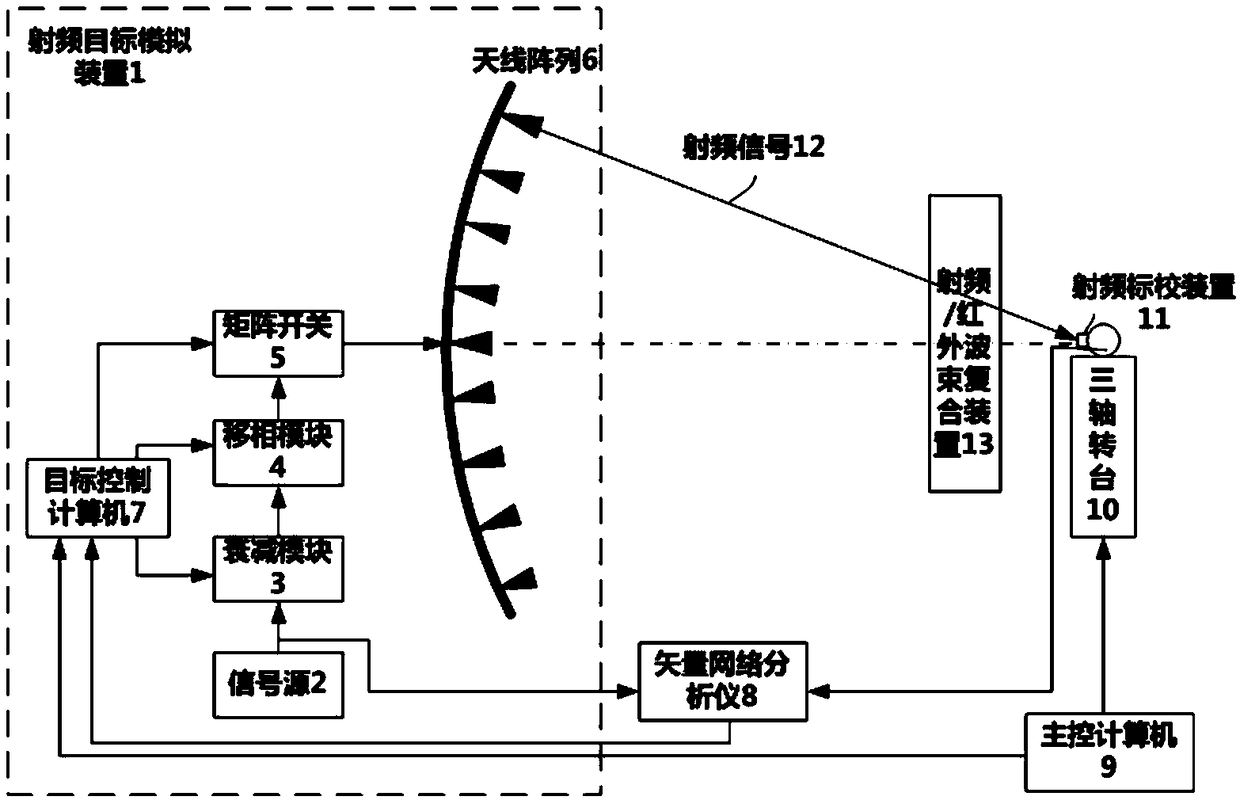
[0049] like figure 1 As shown in the figure, an antenna array radio frequency amplitude and phase error compensation system of the present invention includes a radio frequency target simulation device, a vector network analyzer, a main control computer, a three-axis turntable, a radio frequency calibration device and a radio frequency infrared beam compound device; The radio frequency target simulation device 1 includes a matrix switch 5 , an antenna array 6 , a target control computer 7 , a signal source 2 , an attenuation module 3 , and a phase shift module 4 . Used to generate the simulated target scattered radio frequency signal 12 characteristics, including angle information, intensity characteristics and time characteristics, etc. The RF signal output by the signal source 2 is ...


PUM


Abstract

The invention discloses a system for compensating for an RF amplitude and phase error of an antenna array, and the system comprises an RF target simulation device, a vector network analyzer, a main control computer, a three-axle rotary table, an RF calibration device and an RF infrared beam combination device. The RF target simulation device consists of an antenna array, a matrix switch, a targetcontrol computer, a signal source, an attenuation module and a phase shift module, and is used for generating the simulated target scattering RF signal features. The RF signal outputted by the signalsource is divided into two ways: one way is received by the attenuation module, and the attenuated signal passes through the phase shift module, and then passes through the matrix switch to select a transmitting antenna in the antenna array, and then the transmitting antenna transmits a to-be-simulated RF signal; the other way is transmitted to the vector network analyzer. The system can achieve the compensation for the error caused by the amplitude and phase consistency of an RF signal of an original antenna array after various types of beam combination devices of the plate-shaped macro geometric structures are inserted into a dark room, and improves the characteristics of a working area.

Description

technical field [0001] The invention relates to an antenna array radio frequency signal error compensation method, in particular to a compensation method and system for antenna array radio frequency amplitude and phase errors. Background technique [0002] In order to provide the RF / optical composite detection and guidance system with a physical radiation signal close to the RF / optical characteristics of the real target in the laboratory environment, it is necessary to simultaneously simulate the RF and optical radiation characteristics of the same target. Generally, radio frequency targets are simulated by antenna arrays in darkrooms, while optical targets are simulated by optical target simulators. Since the RF antenna and the optical target simulation device need to generate signals from different positions and directions, the beam recombination device must be used to complete the recombination of the RF signal and the optical signal to ensure that the RF signal and the o...

Claims


Application Information

Patent Timeline
Patent Type & Authority Applications(China)
IPC IPC(8): H04B17/12H04B17/21
CPCH04B17/12H04B17/21
Inventor 田义张励李艳红杨扬朱伟华冯晓晨王立权庞旭东赵吕懿唐成师张宇史松伟孙刚
Owner SHANGHAI INST OF ELECTROMECHANICAL ENG
Why Eureka
Try Eureka