A method of using a microwave thawing device
A kind of equipment and microwave technology, applied in the field of microwave thawing equipment, can solve the problems of reduced energy utilization, weakened suppression section, and low space utilization
- Summary
- Abstract
- Description
- Claims
- Application Information
AI Technical Summary
Problems solved by technology
Method used
Image
Examples
Embodiment 1
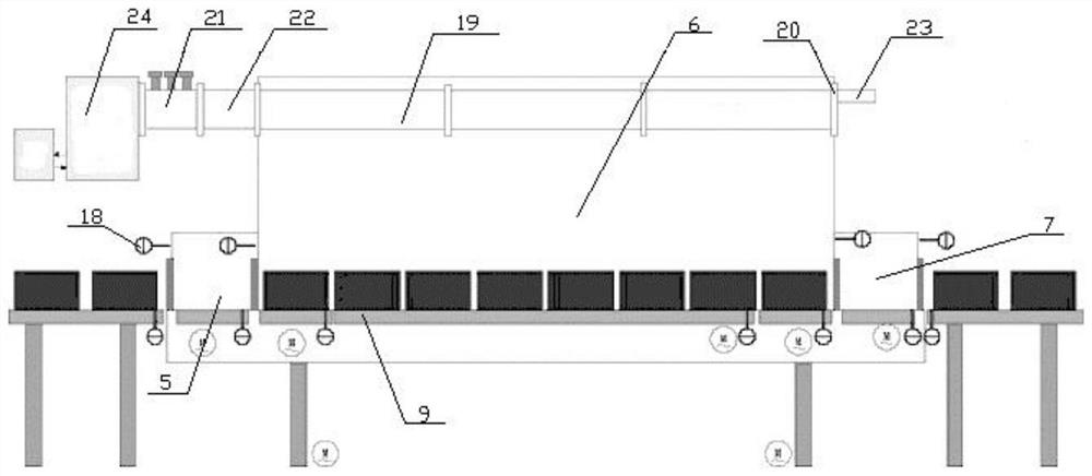
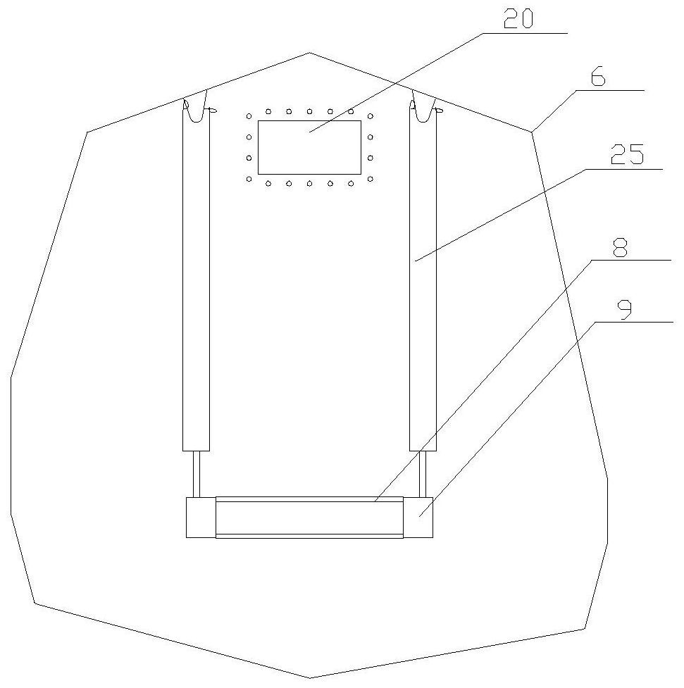
[0036] Embodiment 1: as Figure 1 to Figure 5 As shown, a microwave thawing equipment includes a bracket 1, a microwave heating device, a microwave generator 24 and a control system, the microwave heating device is fixedly arranged on the bracket 1, and the microwave heating device includes successively connected A material suppression chamber 5, a heating chamber 6 and a discharge suppression chamber 7, the heating chamber 6 is provided with a slot antenna 19, and the communication port between the feed suppression chamber 5 and the heating chamber 6 is provided with a first The inner screen door mechanism 10, the port of the feed suppression chamber 5 far away from the heating chamber 6 is provided with a first outer screen door mechanism 11, the communication port between the discharge suppression chamber 7 and the heating chamber 6 A second inner shield door mechanism 12 is provided, and a second outer shield door mechanism 13 is provided at the port of the discharge suppr...
Embodiment 2
[0067] Embodiment 2: be the preferred embodiment of embodiment 1
[0068] The difference with embodiment 1 is characterized in that:
[0069] Preferably, when the length of the microwave thawing device is 8m, the length of the feed suppression chamber 5 and the discharge suppression chamber 7 is reduced to 1m, the length of the heating chamber 6 is increased to 6m, and the length of the corresponding slot antenna 19 is also 6m, Such as Figure 6 As shown, the number of apertures 1901 provided on the slot antenna 19 is preferably 27. Preferably, the distance d between the centers of two adjacent apertures 1901 is 218.72 mm, the angle α between the apertures 1901 and the horizontal line is 10.5°, and the total number of apertures The length L is 144.8mm, and the width W is 25mm.
[0070] Such as Figure 5 As shown, there is also a supporting cross bar for supporting the entire second connecting section 2 .
[0071] Specifically, the waveguide antenna 19 is a slot antenna, an...
Embodiment 3
[0074] A method of using microwave thawing equipment, said microwave thawing equipment is the microwave thawing equipment described in embodiment 1 or 2, and its using method comprises
[0075] Step 1: Turn on the microwave generator 24, and the microwave generated by the microwave generator is transmitted into the heating cavity 6 through the aperture 1901 on the slot antenna 19;
[0076] Step 2: the control system controls the first outer screen door mechanism 11 to open, the material to be defrosted is input into the feed suppression chamber 5, and the control system controls the first outer screen door mechanism 11 to close;
[0077]Step 3: The control system controls the first inner shield door mechanism 10 and the second inner shield door mechanism 12 to open at the same time, and the material to be thawed in the feed suppression chamber 5 is input into the heating chamber 6, and at the same time The thawed material in the heating chamber 6 is output to the discharge sup...
PUM
 Abstract
Description
Claims
Application Information
 - R&D
- Intellectual Property
- Life Sciences
- Materials
- Tech Scout
- Unparalleled Data Quality
- Higher Quality Content
- 60% Fewer Hallucinations
Browse by: Latest US Patents, China's latest patents, Technical Efficacy Thesaurus, Application Domain, Technology Topic, Popular Technical Reports.
© 2025 PatSnap. All rights reserved.Legal|Privacy policy|Modern Slavery Act Transparency Statement|Sitemap|About US| Contact US: help@patsnap.com


