
Device for producing anesthesia breathing mask

A technology for production equipment and breathing masks, which is applied in the direction of breathing masks, medical equipment, and other medical equipment, can solve problems affecting production efficiency, affecting filter accuracy, and affecting production progress, and achieves simple structure, convenient operation, and The effect of improving work efficiency

Inactive Publication Date: 2019-01-22
湖南利德森医疗器械有限公司
View PDF0 Cites 2 Cited by
  • Summary
  • Abstract
  • Description
  • Claims
  • Application Information

AI Technical Summary

Problems solved by technology

[0004] The disadvantage of the existing filter device is: as the use time becomes longer, more and more impurities will accumulate on the filter screen, thereby affecting the filtration accuracy of the filter screen. Once the impurities enter the die head, the die head must be removed. It is labor-intensive and time-consuming, and after the disassembly and assembly of the die, the machine has to go through processes such as heating, heat preservation, and debugging, which is time-consuming and labor-intensive, which affects production efficiency
In view of the above-mentioned shortcomings, the current solution is: after the above-mentioned filter device has been used for a period of time, the fixing block is removed from between the discharge end of the screw extruder and the feed end of the die head, and then the filter screen is replaced. Solution When disassembling the fixed block, it is also time-consuming and labor-intensive, which affects the production schedule

Method used


Image

  • Device for producing anesthesia breathing mask
  • Device for producing anesthesia breathing mask
  • Device for producing anesthesia breathing mask

Examples


Embodiment Construction

[0019] In order to make the technical means, creative features, goals and effects achieved by the present invention easy to understand, the present invention will be further described below in conjunction with specific embodiments.

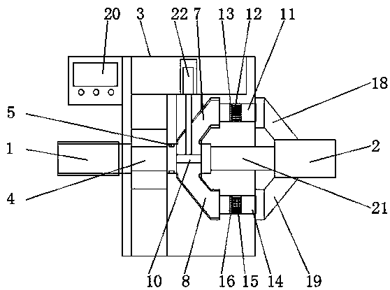
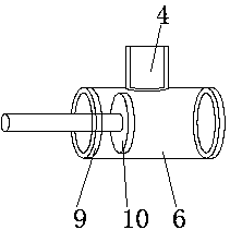
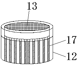
[0020] Such as Figure 1-4 As shown, a production device for an anesthesia breathing mask comprises a fixed cavity 3 arranged between the discharge end 1 of the screw extruder and the feed end 2 of the die head, the discharge end 1 of the screw extruder runs through and is fixed One side wall of the cavity 3 is connected with a transition pipe 4, the inner wall of the port of the transition pipe 4 is provided with a pressure sensor 5, the end of the transition pipe 4 is connected with a main pipe 6, and the two ends of the main pipe 6 are respectively connected with The first branch pipe 7 and the second branch pipe 8, the inner walls of both ends of the main pipe 6 are provided with annular retaining rings 9, the top of the main pipe 6 is provide...


PUM


Abstract

The invention discloses a device for producing an anesthesia breathing mask. The device comprises a fixed cavity arranged between a material discharge end of a screw extruder and a material inlet endof a die head, the material discharge end of the screw extruder penetrates through one side wall of the fixed cavity to be connected with a transition pipe, pressure sensors are arranged on the innerwall of the end opening of the transition pipe, a main pipe is connected to the end part of the transition pipe, two ends of the main pipe are connected with a first branch pipe and a second branch pipe, an annular baffle ring is arranged on the inner wall of each of two ends of the main pipe, an oil cylinder is arranged on the top of the main pipe, a piston rod of the oil cylinder penetrates through the first branch pipe to be fixedly connected with a baffle plate, a first material delivery pipe is connected to the end part of the first branch pipe, a first filtering block is arranged insidethe first material delivery pipe, a first filtering net is mounted on one side, close to the first branch pipe, of the first filtering block in an embedding manner, the pressure sensors are electrically connected with the input end of a controller, and the output end of the controller is electrically connected with the oil cylinder. For the device provided by the invention, the work efficiency isgreatly improved under the condition that the production schedule is not influenced.

Description

technical field [0001] The invention relates to the field of medical device manufacturing, in particular to a production device for an anesthesia breathing mask. Background technique [0002] The anesthesia breathing mask is used in conjunction with anesthesia gas and oxygen supply equipment to help patients breathe. The raw material is a special PVC (polyvinyl chloride) material for medical use. PVC material is a non-crystalline material with non-flammability and high strength. , weather resistance and excellent geometric stability. [0003] When the anesthesia breathing mask is made, the PVC material is extruded by the screw extruder and enters the die head, and then enters the mold through the die head to form. When the PVC material is extruded from the screw extruder, it must be filtered by a filter device before entering the die. The structure of the filter device currently used includes a fixed block arranged between the discharge end of the screw extruder and the fe...

Claims


Application Information

Patent Timeline
Patent Type & Authority Applications(China)
IPC IPC(8): A61M16/06
CPCA61M16/06A61M2207/10
Inventor 雷斌宝邓攀雷斌磊
Owner 湖南利德森医疗器械有限公司
Learn More