Supercharge Your Innovation With Domain-Expert AI Agents!

Doming machine mold unloading control system and method

A technology of control system and drop plastic machine, applied in the direction of coating, etc., can solve the problems of not having intelligent and simple operation requirements, unable to meet the mass production of enterprises, and difficult to guarantee the quality of workpiece handicrafts, etc., to achieve unmanned Streamlined production, increased competitiveness, light weight effect

Active Publication Date: 2019-01-22
遂宁市金虹机械厂
View PDF12 Cites 0 Cited by
  • Summary
  • Abstract
  • Description
  • Claims
  • Application Information

AI Technical Summary

Problems solved by technology

[0003] At present, some enterprises still adopt the traditional manual plastic dropping method when producing plastic drop crafts. In addition, there is no uniform heating standard, and it is difficult to guarantee the quality of handicrafts for each workpiece only by personal subjective judgment; in order to accelerate industrial progress and development, people have developed a single-station drip molding machine. The plastic machine is mainly used in the signage industry. It drips glue on the standard surface printed in various sizes and shapes. The glue can be polyurethane or epoxy resin. It plays a protective and decorative role on the printed signs. Packages that can be used in small circuit boards
Compared with the traditional manual plastic drop, it has made significant progress, but it still cannot meet the requirements of mass production of the enterprise, and the color control is not accurate enough, and the operation is troublesome, which seriously restricts the survival and development of the enterprise. The function of the drop plastic machine tool is too large. Single, does not have rich intelligent and simple operation requirements, greatly reduces the efficiency of actual production, wastes energy and human resources

Method used


Image

  • Doming machine mold unloading control system and method
  • Doming machine mold unloading control system and method
  • Doming machine mold unloading control system and method

Examples


Embodiment 1

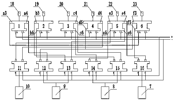
[0031] like Figures 1 to 7As shown in the figure, a mold unloading control system for a plastic dropping machine includes a weak current control system and a strong current control system. The weak current control system includes a signal processor A1, a signal processor B2, a signal processor C3, a signal processor D4, a signal processor Processor E5 and signal processor F6, the strong current control system includes relay A11, relay B12, relay C13, relay D14, relay E15 and relay F16, the signal processor A1 is provided with the first signal transmission pile Aa3 and The second signal transmission pile Aa4, the signal processor B2 is provided with a first signal transmission pile Bb3 and a second signal transmission pile Bb5, and the signal processor C3 is provided with a first signal transmission pile Cc4 and a second signal transmission pile Pile Cc6, the signal processor D4 is provided with the first signal transmission pile Dd4 and the second signal transmission pile Dd5...

Embodiment 2

[0034] like Figures 1 to 7 As shown in the figure, a mold unloading control system for a plastic dropping machine includes a weak current control system and a strong current control system. The weak current control system includes a signal processor A1, a signal processor B2, a signal processor C3, a signal processor D4, a signal processor Processor E5 and signal processor F6, the strong current control system includes relay A11, relay B12, relay C13, relay D14, relay E15 and relay F16, the signal processor A1 is provided with the first signal transmission pile Aa3 and The second signal transmission pile Aa4, the signal processor B2 is provided with a first signal transmission pile Bb3 and a second signal transmission pile Bb5, and the signal processor C3 is provided with a first signal transmission pile Cc4 and a second signal transmission pile Pile Cc6, the signal processor D4 is provided with the first signal transmission pile Dd4 and the second signal transmission pile Dd...

Embodiment 3

[0041] like Figures 1 to 7 As shown in the figure, a mold unloading control system for a plastic dropping machine includes a weak current control system and a strong current control system. The weak current control system includes a signal processor A1, a signal processor B2, a signal processor C3, a signal processor D4, a signal processor Processor E5 and signal processor F6, the strong current control system includes relay A11, relay B12, relay C13, relay D14, relay E15 and relay F16, the signal processor A1 is provided with the first signal transmission pile Aa3 and The second signal transmission pile Aa4, the signal processor B2 is provided with a first signal transmission pile Bb3 and a second signal transmission pile Bb5, and the signal processor C3 is provided with a first signal transmission pile Cc4 and a second signal transmission pile Pile Cc6, the signal processor D4 is provided with the first signal transmission pile Dd4 and the second signal transmission pile Dd...


PUM


Abstract

The invention discloses a doming machine mold unloading control system and method. The system comprises a weak current control system and a strong current control system, and is characterized in thatthe weak current control system comprises a signal processor A, a signal processor B, a signal processor C, a signal processor D, a signal processor E and a signal processor F, and the strong currentcontrol system comprises a relay A, a relay B, a relay C, a relay D, a relay E and a relay F. Through the signal processors, signals are sent to the relays, the relays automatically control cooperative movement among various equipment, compared with all control systems and a traditional numerically-controlled doming machine, the doming machine mold unloading control system has higher precision, operation is visible, the automation degree is high, traditional manual operation is replaced, the efficiency of the doming industry is greatly improved, moreover, a use threshold is low, through a controller, multiple doming devices are controlled to work synchronously, color control is precise, not only is the labor intensity reduced, but also the production efficiency is greatly improved, and theproduct quality is guaranteed.

Description

technical field [0001] The invention belongs to the technical field of mechanical drop molding, and in particular relates to a mold unloading control system and method for a drop molding machine. Background technique [0002] Drop plastic is one of the few products that is still produced by hand in most of the processes. The main raw material is to dissolve PVC paste resin in DOP and other lipids, and add color paste to form a paste resin mixture of different colors. Drop the paste resin mixture of different colors into the aluminum mold, brass mold, electroforming or silicone mold, and by heating to above 170 °C, the PVC paste resin and DOP and other lipids undergo chemical reaction, and become solid and become color. Rich, three-dimensional products. [0003] At present, some companies still use the traditional manual dripping method when producing plastic-dropping handicrafts. This method of plastic-dropping is slow, low in output, and requires a large amount of testing...

Claims


Application Information

Patent Timeline
Patent Type & Authority Applications(China)
IPC IPC(8): B29C41/02B29C41/52B29C41/42
CPCB29C41/02B29C41/42B29C41/52Y02P90/02
Inventor 魏依光
Owner 遂宁市金虹机械厂
Features
  • R&D
  • Intellectual Property
  • Life Sciences
  • Materials
  • Tech Scout
  • Unparalleled Data Quality
  • Higher Quality Content
  • 60% Fewer Hallucinations
Learn More