A small unmanned aerial vehicle adjustable bird claw type mechanical gripper device

A technology of small unmanned aerial vehicles and mechanical grippers, which is applied in the directions of manipulators, aircraft parts, transportation and packaging, etc., and can solve the problem that the structure of the unmanned aerial vehicle's grasping device is complex, cannot meet the daily production needs, and affect the flight stability of the unmanned aerial vehicle and other problems, to achieve the effect of increasing the practical range, obvious grasping effect and light weight

CN109250118APending Publication Date: 2019-01-22SHENYANG UNIV
0 Cites 5 Cited by

Patent Information

Authority / Receiving Office
CN · China
Patent Type
Applications(China)
Current Assignee / Owner
Publication Date
2019-01-22

Smart Images

  • Figure 1
    Figure 1
  • Figure 2
    Figure 2
Patent Text Reader

Abstract

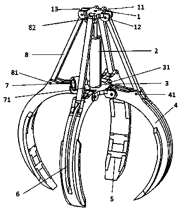
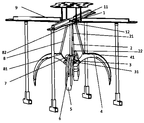
An adjustable bird claw type mechanical gripper device for small unmanned aerial vehicles relates to a mount device for a small unmanned aerial vehicle. A connecting plate of the gripper (1) is a pie-shaped body of a positive cross type. A geometrical center of the pie-shaped body is provided with a threaded hole (11), to connect the power source structure (2), four U-shaped clamping grooves (13)are drawn out in four mutually perpendicular directions on the upper surface of the cake-like body, the spacing dimension of the two solid surfaces of the clamping grooves is consistent with the widthdimension of the head of the power lever, a special-shaped hole (12) is formed on the two solid surfaces of the clamping grooves, and the special-shaped hole (82) on the upper head of the power lever(8) is serially connected with an inner hexagon screw; a grasp center connecting plate (3) is different in shape from a grasp upper connecting plate (1) in that the grasp center connecting plate (3)is provided with a cylindrical center threaded hole (31). The device uses a telescopic rod to control the opening and closing of four grippers, which can control the position and force of gripping stably and accurately, and is more suitable for precise manipulation, and has strong stability and controllability, and obvious gripping effect.
Need to check novelty before this filing date? Find Prior Art

Description

Technical field

[0001] The invention relates to a carrying device for a small unmanned aerial vehicle, in particular to an adjustable bird claw type mechanical gripper device for a small unmanned aerial vehicle. Background technique

[0002] The cross-border integration of UAVs with traditional industries has huge application fields and broad development prospects. "UAV+" will become an important focus of consumer-level explosions, and logistics UAVs are one of them. According to Sohu Technology, the Cainiao ET Logistics Laboratory used drones to complete the first mining and transportation mission of Shifeng Longjing for the first time in March 2018. Companies such as JD.com and Amazon are also stepping up research on drone logistics and distribution technology. However, in the prior art, the UAV still needs to use manpower to load the items on the UAV before taking off. If the items can be automatically loaded, the transportation efficiency will be greatly improved, and the UAV...

Examples

Embodiment Construction

[0017] The present invention will be described in detail below with reference to the embodiments shown in the drawings.

[0018] The lightweight and adjustable "bird claw" mechanical gripper of the present invention includes a gripper connecting plate 1, a power source structure 2, a gripper center connecting plate 3, a bird's claw large joint 4, a bird's claw small joint 5, and a concave notch 6. , Push rod connection port 7, power rod 8. The bird's claw joint 4, the bird's claw small joint 5, and the concave notch 6 are connected to form a single bird's claw structure. The bird's claw joint 4, the bird's claw small joint 5 and the gripper center connecting plate 3 are connected to form the bottom mechanism of the gripper , The power source structure 2 is respectively connected to the gripper connecting plate 1 and the gripper center connecting plate 3, and the power rod 8 connects the gripper connecting plate 1 and the gripper center connecting plate 3 to form the entire graspi...