Safety textile machine

A textile machine, safety technology, applied in the direction of textile, loom, spinning machine, etc., can solve the problems of adaptation, poor versatility, damage to the anti-pinch device, etc., to achieve flexible installation position, improved versatility, and strong versatility Effect

Inactive Publication Date: 2019-01-22
周芹花
1 Cites 0 Cited by

AI-Extracted Technical Summary

Problems solved by technology

Therefore, anti-trap is not realized in the true sense
At the same time, because the ball is in the environment of continuous beating and friction with the semicircular groove, it is very easy to cause damage to the anti-pinch device
[0004] 2. This anti-clamping device cannot be adapted to different sizes of motor output ends and power receiving ends of the shaft, and can only choose fixed-size motor output shafts and...

Method used

In addition, the third biggest difference of the present invention is that, in order to improve the versatility of the connection section with different motor output ends and shafts, as shown in Figure 1, the connection section is facing away from the mounting base 1 The direction gradually becomes smaller, and the connecting section is composed of three-stage connecting parts 34 distributed in a ladder shape, each connecting part 34 is provided with a connecting convex key 35 . The diameters of the connecting parts 34 at the third stage are preferably 20 mm, 35 mm and 50 mm respectively. The three-stage connection part 34 provided in the connection section of the present invention can adapt to three kinds of gears with different apertures, and transmit power through the gears, which not only has good stability. Moreover, the staff can install gears of different specifications on different parts of the connecting section to meet various needs. It can be widely adapted to various m...

Abstract

The invention relates to the technical field of textile and aims to provide a safety textile machine convenient in height adjusting. According to the technical scheme, the safety textile machine is characterized in that an anti-pinch device is arranged on a power transmission path between a prime motor and a shaft and comprises a mounting seat, a main shaft and an auxiliary shaft, one ends of themain shaft and the auxiliary shaft are opposite to each other, the mounting seat comprises two semicircular seat bodies, connecting lugs are arranged at the tops and the bottoms of the seat bodies, the connecting lugs are provided with second bolt holes, the two seat bodies are connected through second bolts penetrating the second bolt holes, and mounting plates are arranged on the outward faces of the bottom connecting lugs of the seat bodies; a lifting component is arranged below the mounting seat and comprises a top plate, a bottom plate and a scissor jack arranged between the top plate andthe bottom plate. The safety textile machine has the advantages that the height of the mounting seat can be adjusted so as to change the overall height of the anti-pinch device, and the safety textile machine is high in universality.

Application Domain

LoomsContinuous wound-up machines

Technology Topic

EngineeringPower transmission +2

Image

  • Safety textile machine
  • Safety textile machine
  • Safety textile machine

Examples

  • Experimental program(1)

Example Embodiment

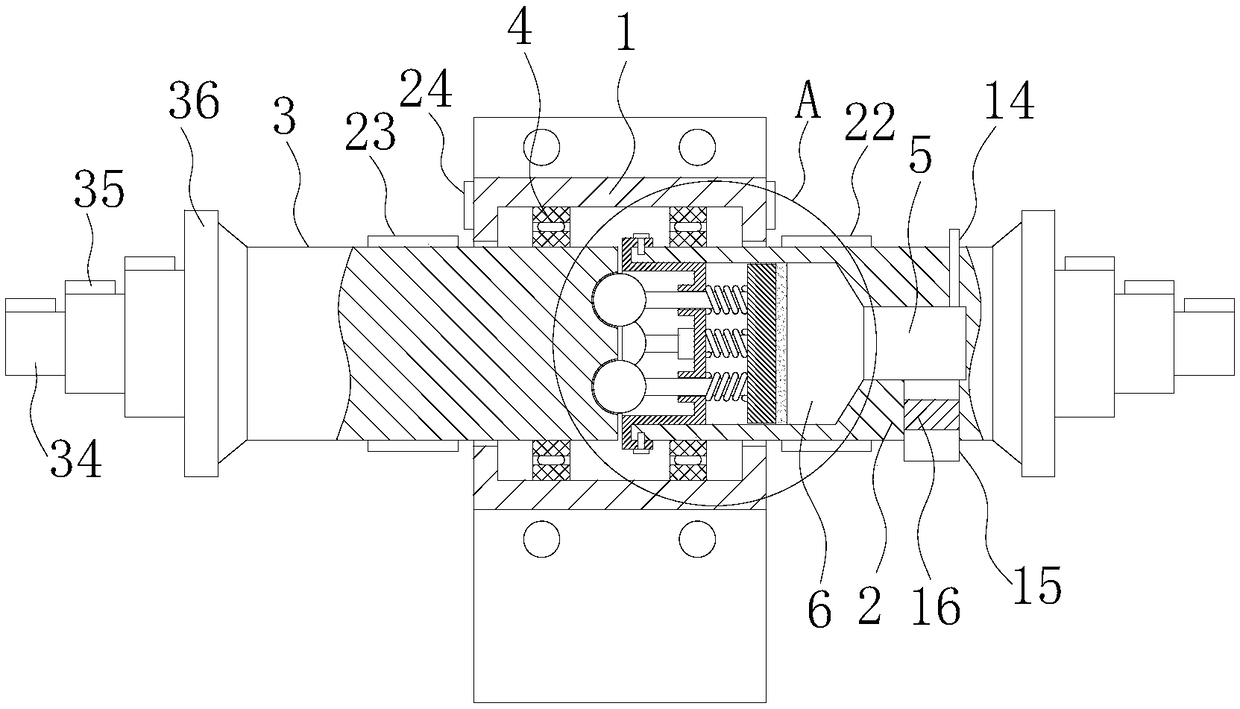
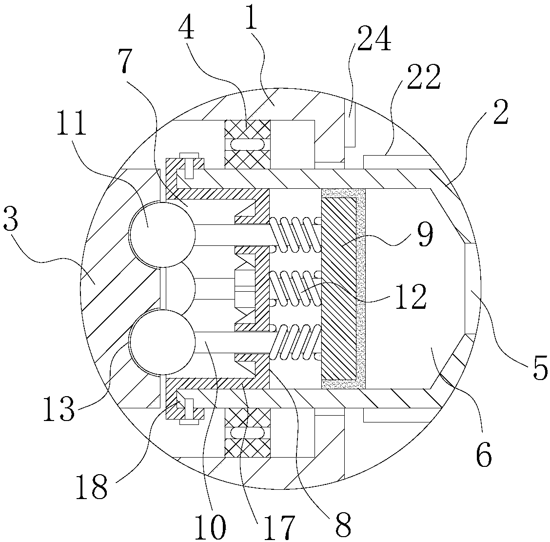
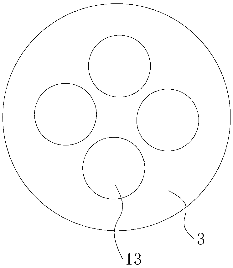
[0025] Such as Figure 1-6 As shown in a safety type textile machine, the power transmission path between the prime mover of the textile machine and the shaft is provided with an anti-pinch device. The prime mover can be an oil extraction machine, a gasoline engine, a motor, etc., generally Motor; The shaft is the shaft that uses power, such as the conveyor shaft, reel, and wheel shaft of a textile machine. The anti-pinch device of the present invention is used to connect the motor and the shaft, transmit the power of the motor to the shaft, and perform abnormal protection. Such as figure 1 As shown, the anti-pinch device includes a mounting seat 1 and a main shaft 2 and a secondary shaft 3 opposite to one end. The mounting seat 1 is in the shape of a sleeve, which is sleeved on the opposite side of the main shaft 2 and the counter shaft 3, and is connected to the main shaft 2 and the counter shaft 3 through the bearings 4, and the opposite ends of the main shaft 2 and the counter shaft 3 are respectively provided There is a connecting section for connecting with the prime mover and the shaft transmission, which is basically the same as the prior art, and will not be repeated here.
[0026] Compared with the prior art, the anti-pinch device of the present invention has the first major difference in that it combines figure 1 with 2 As shown, the main shaft 2 is provided with an exhaust cavity 5 at a position close to the connecting section, and the main shaft 2 is provided with a circular cavity 6 at a position close to the secondary shaft 3, and the exhaust cavity 5 and the cavity 6 communicate with each other. . The cavity 6 extends to the end surface of the main shaft 2 facing the secondary shaft 3, that is, the left end surface of the main shaft 2 in the figure, and forms an opening 7.
[0027] A guide plate 8 and a piston plate 9 are sequentially arranged in the cavity 6 along the direction away from the opening 7, such as figure 2 As shown in the figure, the guide plate 8 is on the left and the piston plate 9 is on the right. The guide plate 8 is relatively fixed to the inner wall of the cavity 6, and the guide plate 8 is evenly provided with a plurality of guide holes around the center. In other words, the position of the guide plate 8 is fixed in the position of the main shaft 2, and the guide plate 8 is provided with a guide hole. The piston plate 9 cooperates with the cavity 6, and the piston plate 9 and the cavity 6 form a piston structure that moves axially along the cavity 6, and the sealing fit between the piston plate 9 and the inner wall of the cavity 6 can be referred to Of course, the piston structure of the automobile engine can also refer to the structure of the syringe.
[0028] A guide rod 10 is inserted into the guide hole on the guide plate 8. One end of the guide rod 10 is fixed to the piston plate 9 and the other end is fixedly provided with a contact 11, and the guide rod 10 passes through the guide hole While guiding, the main shaft 2 can transmit the rotational force to the guide rod 10 through the guide plate 8 during the rotation. For this reason, in order to ensure the stability of power transmission, it is better to do that the hole wall of the guide hole extends toward the end away from the pull-back spring 12 to form a guide short tube 20, and the inner wall of the guide tube 20 contacts the guide rod 10, Disperse stress and improve stability. On this basis, in order to further improve the structural strength of the short guide tube 20, a plurality of triangular reinforcing ribs 21 are arranged between the side wall of the guide short tube 20 and the guide plate 8. The guiding short tubes 20 are evenly distributed in a ring shape.
[0029] The guide rod 10 of the present invention is sheathed with a pull-back spring 12, the pull-back spring 12 is located between the guide plate 8 and the piston plate 9, and both ends of the pull-back spring 12 are fixed to the guide plate 8 and the piston plate 9 respectively. Then, the resilient force of the pull-back spring 12 is used to press the contact head 11 toward the secondary shaft 3. A plurality of contact grooves 13 matched with the contact heads 11 are provided on the end surface of the secondary shaft 3 facing the main shaft 2 corresponding to the contact heads 11, and the contact heads 11 extend into the contact grooves 13. The contact head 11 and the contact groove 13 of the present invention should satisfy a relatively smooth transition relationship. Under normal circumstances, the bridge between the main shaft 2 and the secondary shaft 3 can be ensured. When the resistance of the secondary shaft 3 suddenly increases, the contact head 11 can be removed from Extrusion in contact groove 13, under normal circumstances, such as figure 2 As shown in the figure, the contact head 11 is spherical, and the contact groove 13 is hemispherical. The most ingenious feature of the present invention is that the main shaft 2 is also provided with a suction micropipe 14 and a thick exhaust pipe 15, and the exhaust cavity 5 is in communication with the outside through the suction micropipe 14 and the thick exhaust pipe 15. The thick exhaust pipe 15 is provided with a one-way valve 16 connecting the exhaust cavity 5 to the outside in one direction.
[0030] In the present invention, the connecting section of the main shaft 2 is connected with the prime mover, and the connecting section of the counter shaft 3 is connected with the shaft. In normal use, the prime mover drives the main shaft 2 to rotate. The power of the main shaft 2 is transmitted to the secondary shaft 3 through the guide plate 8, the guide rod 10 and the contact head 11, and the secondary shaft 3 drives the shaft to rotate. When foreign matter enters the mechanical parts of the shaft, the resistance to the shaft rotation increases. At this time, the contact head 11 overcomes the elastic force of the pull-back spring 12 and retracts toward the main shaft side, which in turn drives the guide rod 10 and the piston plate 9 in the air. The cavity 6 moves in the direction of the exhaust cavity 5. At this time, the air in the exhaust cavity 5 is discharged through the thick exhaust pipe 15, but at this time, because the one-way valve 16 is provided in the thick exhaust pipe 15, the outside air cannot quickly fill the exhaust through the thick exhaust pipe 15 In the cavity 5, the inhalation microtube 14 can only enter the exhaust cavity 5 very slowly, so that the pull-back spring 12 cannot prompt the contact head 11 to return in a short time, so that the main shaft 2 and the auxiliary shaft 3 Completely disconnected, leaving ample time for the staff to take emergency operations, and there will be no intermittent collapse. Therefore, the present invention realizes the anti-pinch and release card in a real sense, and has higher safety performance. The guide hole, the guide rod 10, the contact head 11 and the pull-back spring 12 of the present invention can be provided in four groups, of course, the designer can also increase or decrease according to actual needs. In addition, in order to ensure that the air in the cavity 6 can smoothly enter the exhaust cavity 5, a smooth transition between the cavity 6 and the exhaust cavity 5 is made through a tapered surface.
[0031] In order to improve the efficiency of disassembly and assembly of the components in the main shaft 2, a better method of the present invention can also be, such as figure 2 As shown, the opening 7 of the main shaft 2 is also provided with an inner cylinder 17 with one end closed and one end open. The inner cylinder 17 is matched with the cavity 6, that is to say, the diameter of the inner cylinder 17 is equal to the diameter of the cavity 6. quite. Such as Figure 4 As shown, the peripheral surface of the open end of the inner cylinder 17 is provided with a clamping groove 18 that matches the edge of the opening 7 of the main shaft 2. The inner cylinder 17 is inserted into the cavity 6 through the opening 7 of the main shaft 2, and the clamping groove 18 is clamped on the edge of the opening 7 of the main shaft 2. The inner cylinder 17 is detachably connected to the main shaft 2, and the guide The plate 8 is constituted by the bottom of the inner tube 17. The specific detachable connection method may be that the clamping groove 18 of the inner cylinder 17 is threadedly connected to the opening 7 of the spindle 2, but it should be noted that the locking direction of the thread should be consistent with the rotation direction of the spindle 2 to Prevent the main shaft 2 from loosening the threaded connection between the clamping groove 18 and the main shaft 2 during the rotation. But it can also be like figure 2 with 4 As shown, the outer side of the clamping groove 18 and the edge of the opening 7 of the spindle 2 are correspondingly provided with a plurality of first bolt holes 19, and the inner cylinder 17 and the spindle 2 pass through the first bolt hole 19 The first bolt in the bolt hole 19 forms a detachable connection.
[0032] Further, after the fault is resolved, the present invention needs to align the contact head 11 with the contact groove 13 when the machine needs to be restarted, so that the contact head 11 extends into the contact groove 13, in order to facilitate the alignment of the contact head 11 and the contact groove 13, such as figure 1 As shown, the main shaft 2 of the present invention is uniformly provided with a plurality of first indicator keys 22 on the peripheral surface of the mounting seat 1, and the number of the first indicator keys 22 corresponds to the contact head 11, generally four. A plurality of second indicator keys 23 are uniformly provided on the peripheral surface of the secondary shaft 3 close to the mounting seat 1, and the number of the second indicator keys 23 corresponds to the contact groove 13, generally four. Two indicating arrows 24 are correspondingly provided on the end surfaces of the two ends of the mounting seat 1. When the contact head 11 extends into the contact groove 13, the indicating arrows 24, the first indicating key 22 and the second indicating key 23 are located in the same straight line on. In this way, the worker can rotate the secondary shaft 3 and the main shaft 2 to make one set of the first indicator key 22 and the second indicator key 23 align with the indicator arrow 24 before restarting the machine.
[0033] The second major difference of the present invention is that, in order to improve the convenience and versatility of installation of the anti-pinch device of the present invention, such as Figure 5 with 6 As shown, the mounting seat 1 includes two semicircular seat bodies 25, the semicircular shape is substantially a semi-cylindrical shape, and the two seat bodies 25 together constitute the main body of the mounting seat 1. Both the top and bottom of the seat body 25 are provided with connecting ears 26, the connecting ear 26 is provided with a second bolt hole 27, and the second bolt hole 27 passes through the second bolt hole 27 between the two seat bodies 25. For bolt connection, in order to improve the stability of the connection between the two seat bodies 25, a rubber gasket 33 is sandwiched between the connecting ears 26 of the two seat bodies 25. Of course, the rubber gasket 33 is also provided with a second Two bolt hole 27. A mounting plate 28 is provided on the outer side of the connecting ear 26 at the bottom of the seat body 25. A lifting assembly is provided under the mounting base 1, and the lifting assembly is composed of a top plate 29, a bottom plate 30 and a scissor jack 31 arranged between the top plate 29 and the bottom plate 30. The mounting plate 28 and the top plate 29 are provided with a plurality of sets of third bolt holes 32 correspondingly, and the mounting plate 28 and the top plate 29 are connected by third bolts passing through the third bolt holes 32.
[0034] The mounting seat 1 of the present invention is composed of two seat bodies 25, which facilitates the assembly of the bearing 4, the main shaft 2 and the counter shaft 3. At the same time, the scissor jack 31 can be used to quickly adjust the overall height of the anti-pinch device to meet various installation requirements. In order to further improve the flexibility of mounting the mounting seat 1 on the top plate 29 and facilitate fine-tuning according to actual conditions, the third bolt hole 32 on the mounting plate 28 is in a strip shape, so the versatility is further improved.
[0035] In addition, the third major difference of the present invention is that in order to improve the versatility of the connecting section with different motor output ends and shafts, such as figure 1 As shown, the connecting section gradually becomes smaller toward the direction away from the mounting seat 1, and the connecting section is composed of three-stage connecting portions 34 distributed in a stepped manner. Each connecting portion 34 is provided with a connecting convex key 35 . The diameters of the three-stage connecting portion 34 are preferably 20 mm, 35 mm, and 50 mm, respectively. The three-stage connecting portion 34 provided in the connecting section of the present invention can adapt to gears with three different apertures, and transmit power through the gears, which not only has good stability. Moreover, the staff can install gears of different specifications in different parts of the connecting section to adapt to various needs, and can be widely adapted to various different motor models and shaft models. It has excellent versatility and is convenient for existing The textile machines were renovated and updated. In order to prevent the gear from moving on the connecting portion 34 of the largest stage, a limit disk 36 is provided on the rear side of the largest one of the connecting portions 34 of the third stage.

PUM

no PUM

Description & Claims & Application Information

We can also present the details of the Description, Claims and Application information to help users get a comprehensive understanding of the technical details of the patent, such as background art, summary of invention, brief description of drawings, description of embodiments, and other original content. On the other hand, users can also determine the specific scope of protection of the technology through the list of claims; as well as understand the changes in the life cycle of the technology with the presentation of the patent timeline. Login to view more.

Similar technology patents

Method for carrying out cluster management on network equipment based on SNMP protocol

InactiveCN1885858ASave public network ip address resourcesVersatile
Owner:CHINA GREATWALL TECH GRP CO LTD

Servo hydraulic transmission mechanism

InactiveCN101839258AAvoid hidden dangers of mechanical failureVersatile
Owner:宋家骏

Classification and recommendation of technical efficacy words

  • Versatile
  • flexible change

Automobile electric control unit calibration system and method based on ASAP standard

InactiveCN101334662AVersatileResolve interface mismatch
Owner:CHONGQING UNIV OF POSTS & TELECOMM

Multi-bus automobile communication control module based on TCN

ActiveCN1889494AaccelerateVersatile
Owner:ZHUZHOU CSR TIMES ELECTRIC CO LTD

Variable capacity multi-cylinder rotary compressor and its running method

InactiveCN1955476Alow costVersatile
Owner:LG ELECTRONICS (TIANJIN) APPLIANCES CO LTD

Tunable laser based on dual interference of dual-core optical fiber and Sagnac ring

InactiveCN111711056AIncreased output wavelength tunable rangeflexible change
Owner:BEIJING JIAOTONG UNIV
Why Eureka
Try Eureka