Eureka AIR delivers breakthrough ideas for toughest innovation challenges, trusted by R&D personnel around the world.

Double-chamber oocyte collector

An oocyte and collector technology, applied in the field of medical devices, can solve the problems of unclear ultrasound imaging, real-time observation of the depth of needle insertion, and reduced effectiveness, and achieve good surface finish, good puncture somatosensory, and reduced puncture resistance. Effect

Active Publication Date: 2019-01-25
SHANGHAI KANGDELAI ENTERPRISE DEV GRP CO LTD
View PDF10 Cites 3 Cited by
  • Summary
  • Abstract
  • Description
  • Claims
  • Application Information

AI Technical Summary

Problems solved by technology

Although, in a puncture needle disclosed in patent 200610066108.6, a sharper ultrasonic imaging can be obtained up to the tip end of the puncture needle. Concave machining of the needle periphery will result in less clear ultrasound visualization up to the end of the needle tip, reducing the effectiveness of this method
[0013] In addition, during the egg retrieval operation, especially when the puncture is in progress, the operator often needs to move his sight from the display screen to the puncture needle, and confirm the depth of the needle by observing the puncture needle on his hand, which is very inconvenient for the doctor to operate. It also affects the accuracy of the operation
It is well known that the effective length of the puncture needle used in the egg retrieval operation is relatively long, about 30cm to 35cm. Even if the ultrasound imaging of the needle head of the puncture needle in the existing technical solution is clearly identifiable, it is difficult to develop the other parts of the puncture needle without special treatment. Doctors cannot directly observe the depth of needle insertion on the display screen in real time, which also reduces the accuracy of surgical operations

Method used


Image

  • Double-chamber oocyte collector
  • Double-chamber oocyte collector
  • Double-chamber oocyte collector

Examples


Embodiment Construction

[0041] In order to enable those skilled in the art to better understand the technical solution of the present invention, its specific implementation will be described in detail below in conjunction with the accompanying drawings:

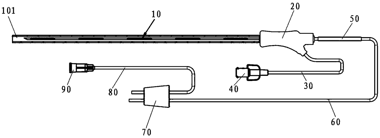
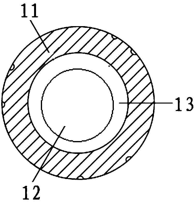
[0042] see figure 1 , Figure 1a , Figure 2a and Figure 2b , a double-chamber oocyte collector of the present invention, comprising a puncture needle 10, a handle 20, an irrigation catheter 30, a locking joint 40, a catheter sleeve 50, a suction catheter 60, a silicone plug 70, a vacuum catheter 80 and a conical joint 90 , the puncture needle 10 is sleeved with a protective cover 101, the puncture needle 10, the handle 20, the catheter sleeve 50, the suction catheter 60 and the silicone plug 70 are connected in sequence, the locking joint 40 is connected with the handle 20 through the flushing catheter 30, and the conical joint 90 passes through A vacuum conduit 80 is connected to the silicone stopper 70 .

[0043] The puncture needle 10 inclu...


PUM


Abstract

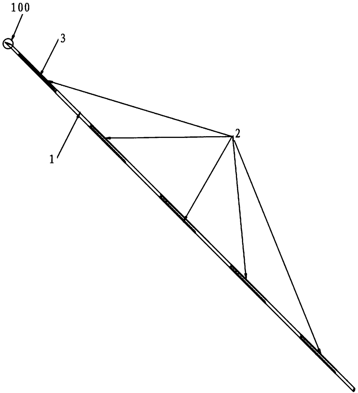
The invention discloses a double-chamber oocyte collector, the double-chamber oocyte collector comprises a puncture needle, a handle, a flushing catheter, a locking joint, a catheter sleeve, a suctioncatheter, a silicone plug, a vacuum catheter and a conical joint, the puncture needle comprises an inner needle and an outer needle arranged coaxially from the inside to the outside, the outer needlecomprises a needle tube and a needle tip connected with the needle tube, and an ultrasonic development enhancement band group is arranged on the outer wall surface of the needle tube; the needle tubeadopts an equal-diameter needle tube; and the set of ultrasonic development enhancement bands comprises a plurality of ultrasonic development enhancement bands, and the plurality of ultrasonic development enhancement bands are sequentially distributed on the outer wall surface of the needle tube along the axial equal spacing of the needle tube. The double-chamber oocyte collector of the inventionenables the ultrasonic imaging of the puncture needle to present a light-dark alternating scale, and is easy for the operator to directly observe the needle feeding depth on the display screen of theultrasonic imaging system in real time during the operation, so that the operation is more accurate.

Description

technical field [0001] The invention relates to a double-cavity oocyte collector, which is used for human assisted reproductive technology (ART) ultrasound imaging-guided oocyte retrieval, and belongs to the field of medical devices. Background technique [0002] In the medical field, guided by ultrasound images, puncture is used to puncture the target site to collect body fluids, tissues, cells or introduce medicinal liquid. During the operation, the doctor places the ultrasound probe on the site to be punctured or on the body surface of the site to be punctured, and inserts the needle from the side of the probe. On the display screen of the imaging system, the tissue structure, needle and needle tip can be seen, so as to accurately grasp the puncture needle to reach the target position. In the actual operation process, since the outer wall of the puncture needle is smooth, it produces mirror reflection to the incident sound wave, and the smaller the angle between the punc...

Claims


Application Information

Patent Timeline
Patent Type & Authority Applications(China)
IPC IPC(8): A61B17/42A61B17/435A61B34/20
CPCA61B17/42A61B17/435A61B34/20A61B2034/2063
Inventor 李军生张宇黄春辉
Owner SHANGHAI KANGDELAI ENTERPRISE DEV GRP CO LTD
Why Eureka
Eureka Blog
Learn More