CNC (computer numerical control) machining center

A machining center and mounting plate technology, applied in metal processing equipment, metal processing mechanical parts, manufacturing tools, etc., can solve problems such as inability to complete parts, unreliable support of support points, and reliable clamping, etc., so as to facilitate replacement and save Processing process to ensure the effect of stable support

Pending Publication Date: 2019-01-25
苏州丰川电子科技有限公司
View PDF0 Cites 2 Cited by
  • Summary
  • Abstract
  • Description
  • Claims
  • Application Information

AI Technical Summary

Problems solved by technology

[0003] In the machining process of parts using CNC machining centers, such as the processing of the side cover of a notebook computer, it is necessary to support and position the parts through fixtures, but during the processing of the parts, due to machining er

Method used


Image

  • CNC (computer numerical control) machining center
  • CNC (computer numerical control) machining center
  • CNC (computer numerical control) machining center

Examples


Embodiment 1

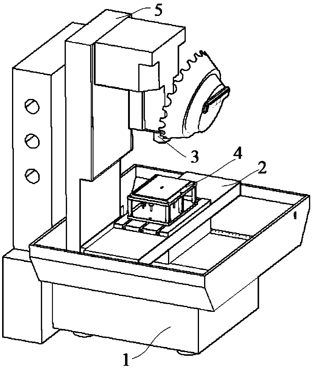
[0038] Embodiment 1: A kind of CNC machining center, including machine base 1, base plate 2, main shaft 3 and clamping jig 4, described base plate 2 is fixed on the machine base 1, and clamping jig 4 is installed on this base plate 2, so The main shaft 3 is installed on the base 1 through a mounting plate 5;

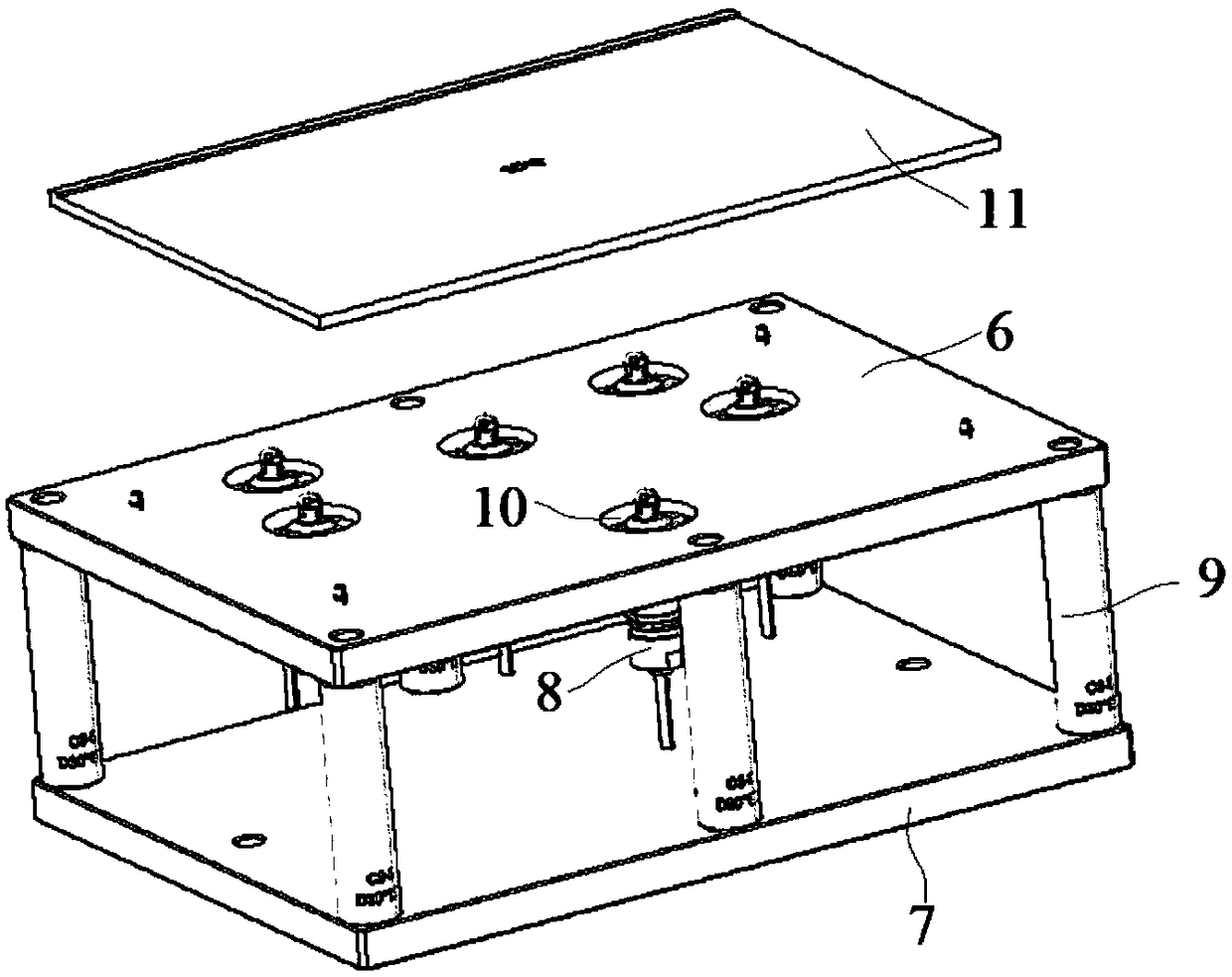
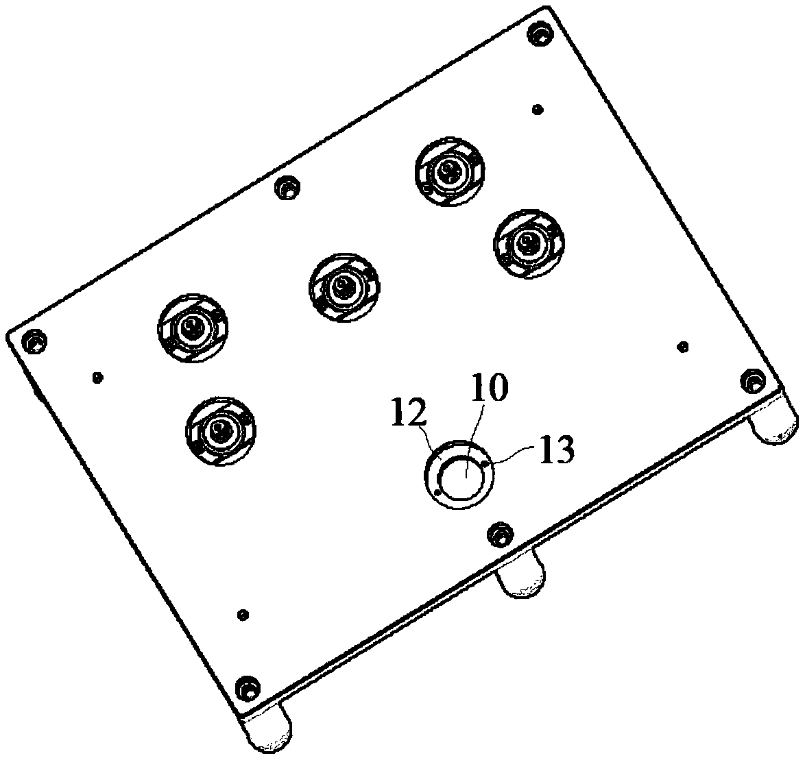
[0039] The clamping fixture 4 includes a first mounting plate 6, a second mounting plate 7 and several support heads 8 arranged in parallel, and the first mounting plate 6 and the second mounting plate 7 are connected by several support columns 9, the A plurality of through holes 10 are provided on the first mounting plate 6, and the upper ends of the support heads 8 protrude from the through holes 10 respectively and are installed and connected with the first mounting plate 6. A workpiece 11 is placed on the top of the first mounting plate 6 and connected with the first mounting plate 6. The support head 8 is contacted and connected;

[0040] The support head 8 include...

Embodiment 2

[0048] Embodiment 2: A kind of CNC machining center, including machine base 1, base plate 2, main shaft 3 and clamping jig 4, described base plate 2 is fixed on the machine base 1, and clamping jig 4 is installed on this base plate 2, so The main shaft 3 is installed on the base 1 through a mounting plate 5;

[0049] The clamping fixture 4 includes a first mounting plate 6, a second mounting plate 7 and several support heads 8 arranged in parallel, and the first mounting plate 6 and the second mounting plate 7 are connected by several support columns 9, the A plurality of through holes 10 are provided on the first mounting plate 6, and the upper ends of the support heads 8 protrude from the through holes 10 respectively and are installed and connected with the first mounting plate 6. A workpiece 11 is placed on the top of the first mounting plate 6 and connected with the first mounting plate 6. The support head 8 is contacted and connected;

[0050] The support head 8 include...


PUM


Abstract

The invention discloses a CNC (computer numerical control) machining center, which comprises a base, a base plate, a spindle and a clamping jig. The base plate is fixed to the base, the clamping jig is mounted on the base plate, and the spindle is mounted on the base through a mounting plate. The clamping jig comprises a first mounting plate, a second mounting plate and a plurality of supporting heads, and the first mounting plate and the second mounting plate are parallel. Upper ends of the supporting heads extend out of through holes to connect with the first mounting plate, each bottom capis connected with the lower end of the corresponding shell, each elastic holding sleeve sleeves the outer side of a corresponding movable ejector rod, each movable sleeve sleeves the outer side of thecorresponding elastic holding sleeve, each elastic holding sleeve and the corresponding movable sleeve are positioned in the corresponding shell, the lower end of each movable sleeve penetrates the corresponding bottom cap to fixedly connect with a corresponding push block, and each push block is connected with a driving mechanism. The CNC machining center is applicable to workpieces under different conditions; when the multiple supporting heads are combined for supporting the workpieces, a down moving distance of the movable ejector rod of each supporting head varies along with lower surfacebending degrees of the workpieces, and structural ingenuity is realized.

Description

technical field [0001] The invention relates to a CNC machining center, which belongs to the technical field of machining precision parts of electronic products. Background technique [0002] Computer numerical control machine tool (CNC for short) is an automatic machine tool equipped with a program control system, which can logically process and decode programs with control codes or other symbolic instructions, so that the machine tool moves and processing parts. CNC is mainly used for large-scale processing parts, and its processing methods include turning outer circle, boring, turning plane, etc. Programs can be written, suitable for mass production, and the production process has a high degree of automation, and is widely used in automobiles, aerospace and military industries. Compared with ordinary machine tools, CNC has high processing precision, stable processing quality, multi-coordinate linkage, and can process parts with complex shapes. When the processed parts a...

Claims


Application Information

Patent Timeline
IPC IPC(8): B23Q3/06B23Q11/00
CPCB23Q3/06B23Q3/062B23Q11/00
Inventor 蒋燕赵长亮周士升詹淳崵
Owner 苏州丰川电子科技有限公司
Why Eureka
Try Eureka