Thermal control system and thermal control method for power station in high and cold region

A technology for thermal control systems and alpine regions, applied in control/regulation systems, non-electric variable control, temperature control using electric methods, etc., can solve problems that cannot affect indoor airflow organization, aggravate energy supply contradictions in alpine regions, and actively control temperature In order to improve the rationality of heat distribution and utilization, alleviate the contradiction between energy supply and demand, and achieve efficient transfer

Inactive Publication Date: 2019-01-25
SOUTHEAST UNIV
View PDF6 Cites 0 Cited by
  • Summary
  • Abstract
  • Description
  • Claims
  • Application Information

AI Technical Summary

Problems solved by technology

[0004] In terms of air temperature control in the power station, traditional designs usually only use exhaust fans to remove excess heat in the power station
Obviously, when the heat generated by the equipment in the power station is large, it is necessary to increase the exhaust air volume to ensure the temperature control effect, which will consume a lot of power
At the same time, since the exhaust fan is installed on the wall of the power station, it cannot affect the indoor airflow organization, and it is easy to accumulate heat in the upper part of the room, resulting in excessively high air temperature above.
[0005] From the above analysis, it can be seen that in the traditional design of power stations in alpine regions, on the one hand, it needs to consume a lot of energy to heat the oil tank and remove indoor waste heat, which exacerbates the energy supply contradiction in alpine regions; The temperature control effect is not ideal

Method used


Image

  • Thermal control system and thermal control method for power station in high and cold region
  • Thermal control system and thermal control method for power station in high and cold region
  • Thermal control system and thermal control method for power station in high and cold region

Examples


Embodiment Construction

[0028] Carry out further detailed description below in conjunction with accompanying drawing:

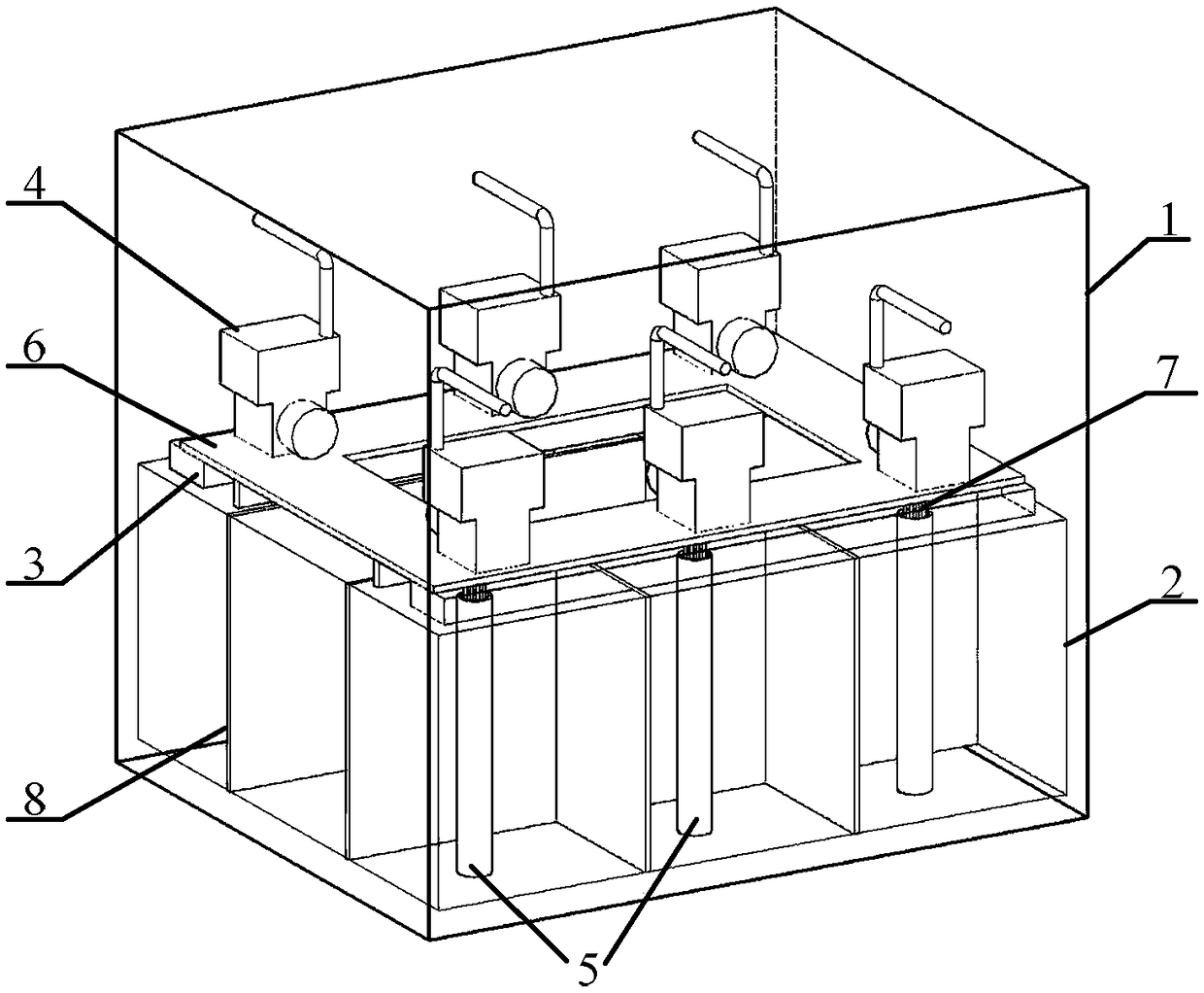
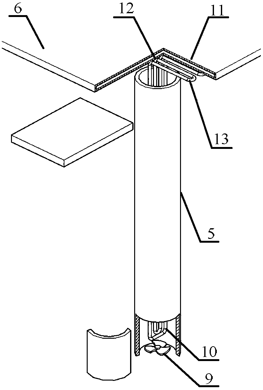
[0029] figure 1 A structural diagram of the thermal control system of a power station in an alpine region is given, including passive temperature control devices and active temperature control devices, figure 2The local details of the junction of the honeycomb structure vapor chamber and the bent loop heat pipe are given. In the power station 1, the honeycomb structure vapor chamber 6 is set as the base of the fuel-fired generator set 4 between the oil storage tank 2 containing the ventilation pipe 5 and the fuel-fired generator set. The shells are in close contact, and the honeycomb structure vapor chamber cooling section 12 is attached to the upper surface of the lubricating oil tank 3 . The bent loop heat pipe 7 is arranged under the fuel oil generating set, the bent loop heat pipe heating section 13 runs through the honeycomb structure vapor chamber cooling section, and the b...


PUM


Abstract

The invention discloses a thermal control system and a thermal control method for a power station in a high and cold region. The thermal control system comprises a passive temperature control device and an active temperature control device, wherein the passive temperature control device comprises a honeycomb structured temperature equalization plate, bent loop heat pipes and a metal grille; the honeycomb structured temperature equalization plate is arranged between an oil storage tank and a fuel generator set; the bent loop heat pipe is arranged under the fuel generator set, heating sections of the bent loop heat pipes are in tight contact with a cooling section of the honeycomb structured temperature equalization plate, and cooling sections of the bent loop heat pipes are vertically inserted into ventilation pipelines and extend to the lower parts of the ventilation pipelines. The thermal control system is based on the heat pipe technology, fully utilizes the high temperature heat source of the fuel generator set, and adopts the active and passive combined thermal control method to transfer the local heat emitted by the fuel generator set to the interior of the entire fuel tank. The thermal control system and the thermal control method improve the energy utilization rate, and realize the economical and effective thermal control of the power station in the high and cold regions.

Description

technical field [0001] The invention relates to a temperature control problem of a power station in an alpine region, in particular to a thermal control system and a thermal control method for a power station in an alpine region. Background technique [0002] The main structure of the power station in the alpine region is that the lower part of the room is the oil storage tank and the lubricating oil tank, and the diesel engine and other equipment are installed above the oil tank. Due to the cold climate in the alpine region, during the operation of the power station, the temperature distribution in the room is hot at the top and cold at the bottom, and the temperature difference is extremely large. Due to the low temperature of the oil storage tank and lubricating oil tank located below the power station, the temperature difference between the upper and lower fuel is very obvious, and the fuel in the low temperature area at the bottom is very prone to solidification and can...

Claims


Application Information

Patent Timeline
Patent Type & Authority Applications(China)
IPC IPC(8): G05D23/19
CPCG05D23/1919
Inventor 陈永平张子文姚峰张程宾
Owner SOUTHEAST UNIV
Why Eureka
Try Eureka