A simulated lung device for emergency care

A technology for simulating lungs and emergency treatment, applied in the field of medical devices, can solve problems that affect the effective use of ventilators, affect patient rescue and treatment, and increase medical costs

Active Publication Date: 2021-06-08
泗水县人民医院
View PDF16 Cites 0 Cited by
  • Summary
  • Abstract
  • Description
  • Claims
  • Application Information

AI Technical Summary

Problems solved by technology

This has seriously affected the effective use of ventilators and affected the rescue and treatment of patients.
[0004] In emergency care, in order to prevent cross-infection between patients, disposable medical appliances are widely used, mechanical ventilation is one of the main treatment methods for emergency patients, and the working status of the ventilator must be checked with a simulated lung before each use And debugging its parameters, it is inconvenient to adjust
In addition, due to the long-term use of the simulation method matched with the ventilator, it is easy to be damaged and expensive, which greatly increases the medical cost.

Method used


Image

  • A simulated lung device for emergency care
  • A simulated lung device for emergency care
  • A simulated lung device for emergency care

Examples


Embodiment 1

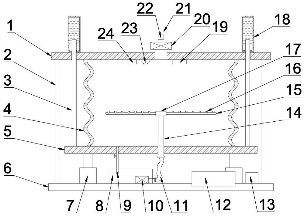
[0029] see Figure 1~3 , in an embodiment of the present invention, a simulated lung device for emergency care, comprising a top plate 1, a fixed rod 2, an air bag 4, a bottom plate 5, a base 6, a telescopic device 7, a capacitive liquid crystal control panel 12, a controller 13 and an exhaust pipe 21. The airbag 4 is made of natural rubber material. The upper and lower ends of the airbag 4 are respectively sealed and fixedly connected to the top plate 1 and the bottom plate 5. A base 6 is provided below the bottom plate 5, and an outer ring passes between the top plate 1 and the base 6. The plurality of fixed rods 2 provided are connected and fixed, and the outer ring between the base plate 5 and the base 6 is also provided with a plurality of telescopic devices 7, which can drive the base plate 5 to move up and down through the telescopic devices 7, and the base 6 is also provided with Water tank 8, the bottom plate 5 is provided with a drain pipe 9, the lower end of the dra...

Embodiment 2

[0032] see figure 1 and 4 The difference between this embodiment and Embodiment 1 is that: the outer ring between the top plate 1 and the bottom plate 5 is also provided with a plurality of guide rods 3, the lower ends of the guide rods 3 are fixed on the bottom plate 5, and the guide rods 3 and The top plate 1 is fitted with a sliding connection, and a damping cylinder 18 is installed on the upper side of the top plate 1. The damping cylinder 18 is a vertical cylindrical cylinder structure, and the guide rod 3 and the damping cylinder 18 are coaxially arranged. The guide rod 3 The upper end of the upper end is located in the damping cylinder 18, and the lower end of the guide rod 3 and the damping cylinder 18 is in a sealed sliding connection. The inner side of the damping cylinder 18 is installed on the guide rod 3 with a plurality of porous dampers that are slidably connected with the inner wall of the damping cylinder 18. plate 29, the damping plate 29 is provided with at...


PUM


Abstract

The invention discloses a simulated lung device for emergency care, which comprises a top plate, a fixed rod, an air bag, a bottom plate, a base, a telescopic device and an exhaust pipe. Connected by a fixed rod, there are multiple telescopic devices between the bottom plate and the base, a vertical pipe is installed in the middle of the bottom plate, and a rotating head is installed on the upper end of the vertical pipe. A plurality of atomizing nozzles are respectively arranged on different sides of the pipe, a hose is connected to the lower end of the vertical pipe, the other end of the hose is connected to the water outlet of the water pump provided at the bottom of the water tank, and an exhaust pipe is installed in the middle of the top plate. The invention is more in line with human lung respiration physiology, reduces the difficulty of equipment operation, makes test results intuitive and visualized, and has extremely high application value in scientific experiment research, respiration physiology teaching, respiration-related product inspection and other occasions.

Description

technical field [0001] The invention relates to the technical field of medical devices, in particular to a simulated lung device for emergency care. Background technique [0002] With the rapid development of my country's medical industry, mechanical ventilation is becoming more and more common in my country's medical institutions, and the share of ventilators in medical institutions is growing rapidly. The rescue of critically ill patients has become the top priority of major general hospitals, and the construction of intensive care units (ICU) is also constantly being strengthened. Among them, the high-end ventilators used to rescue and maintain the lives of patients have been widely used in the treatment of critically ill patients, and play an extremely important role in the rescue of critically ill patients. [0003] With people's continuous understanding of respiratory physiology, various intelligent ventilators that meet the physiological requirements of the human bod...

Claims


Application Information

Patent Timeline
Patent Type & Authority Patents(China)
IPC IPC(8): G09B23/28
CPCG09B23/288
Inventor 张敏张加鹏
Owner 泗水县人民医院
Why Eureka
Try Eureka