Welding strip pulling compressing device and method and series welding machine

A welding ribbon and equipment technology, applied in welding equipment, welding equipment, auxiliary welding equipment, etc., can solve problems affecting product quality, low production efficiency, and easy detachment of welding ribbon, so as to improve welding accuracy, improve work efficiency, The effect of reducing processing time

Pending Publication Date: 2019-01-29
WUXI AUTOWELL TECH
View PDF11 Cites 5 Cited by
  • Summary
  • Abstract
  • Description
  • Claims
  • Application Information

AI Technical Summary

Problems solved by technology

In the traditional welding strip processing method, each action needs to be completed before the previous action is completed, which is time-consuming and has low production efficiency, which does not meet the needs of modern high-tempo production.
Especially when dealing with dense grid welding strips, the welding strips are easy to get out of position, resulting in welding failure and affecting product quality

Method used


Image

  • Welding strip pulling compressing device and method and series welding machine
  • Welding strip pulling compressing device and method and series welding machine
  • Welding strip pulling compressing device and method and series welding machine

Examples


Embodiment 1

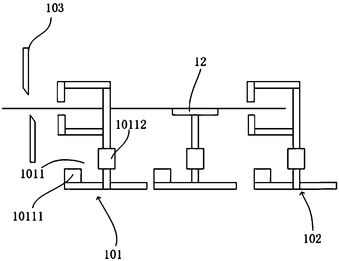
[0055] figure 1 It is a front structural schematic diagram of Embodiment 1 of the traction part in the strip traction and compaction equipment of the present invention. Fig. 2 is a top view structural diagram of Embodiment 1 of the traction part of the strip traction and compaction equipment of the present invention. Such as figure 1 and figure 2 As shown, the pulling part of the ribbon pulling and compacting equipment includes a first pulling device 101 and a second pulling device 102 , and the second pulling device 102 is installed behind the first pulling device 101 .

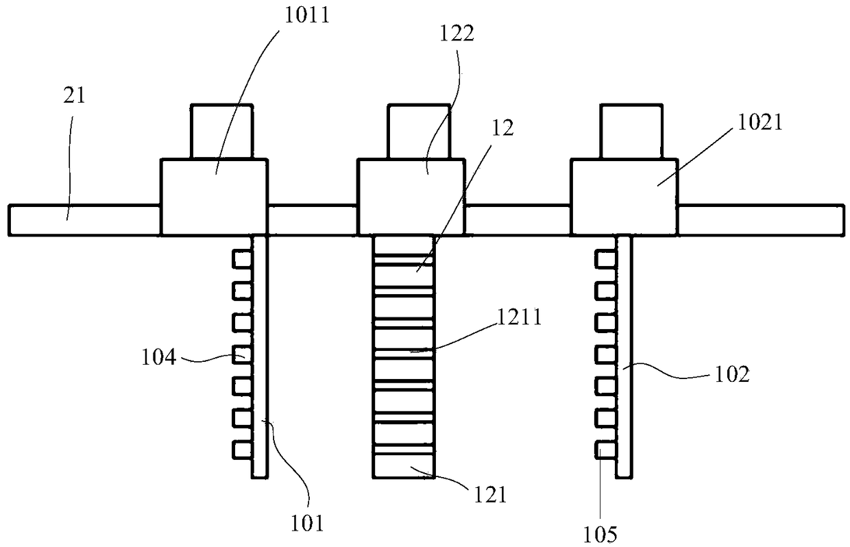
[0056] In this embodiment, a guiding ribbon device 12 is provided between the first pulling device 101 and the second pulling device 102. The guiding ribbon device 12 includes a guiding plate 121 and a guiding moving mechanism 122. At least two a guide groove 1211.

[0057] In this embodiment, the first pulling device 101 includes a first moving mechanism 1011 and a welding belt mechanism 104, wherein t...

Embodiment 2

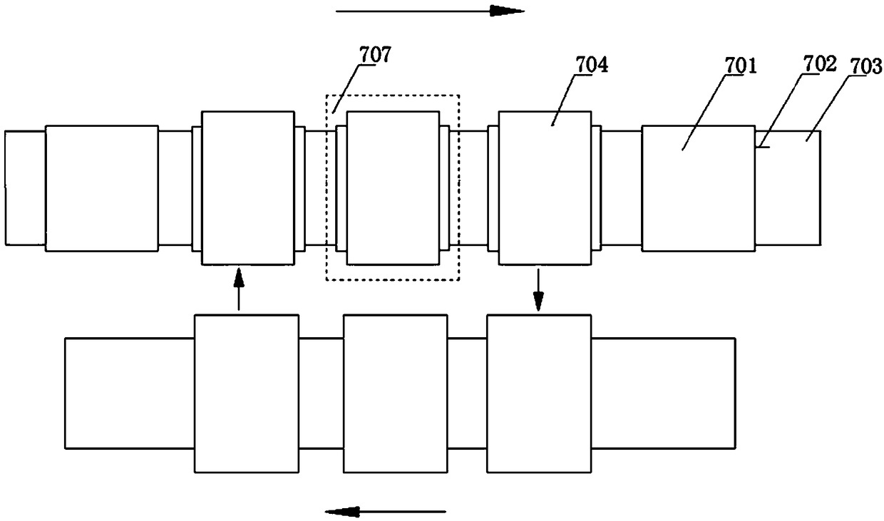
[0062] Such as Figure 3 to Figure 4 As shown in the figure, a battery sheet 701, a welding ribbon 702, a conveying line 703, a net pressing plate 704, a pressing pin 705, a spring 706 and a heating device 707 are shown in the figure. In this embodiment, the pressing pins 705 are arranged in a multi-row array, all of which are installed on the net pressing plate 704, and each row of pressing pins 705 forms a pressing pin group, and each pressing pin group corresponds to each welding ribbon 702 one by one, so that Ensure that each welding strip 702 has the same number of stress points as the number of pressing pins 705 in each row of pressing pins. The number of pressing pins 705 included in each row of pressing pins can be determined according to specific production requirements. For example, it can be Seven, eight, nine, ten, eleven, twelve or other applicable number. In addition, a spring 706 can be sleeved on each pressing pin 705 to form an elastic pressure, so as to ensu...

Embodiment 3

[0069] Such as Figure 5 and Figure 6 As shown, this embodiment includes a support plate 70010 , at least one support bar 70020 mounted on the support plate 70010 and at least one pressing pin 70030 mounted on the support bar 70020 . combined reference Figure 6 The indenter 70030 includes a sleeve 70031, an indenter head 70032 and a spring 70033, the upper end of the sleeve 70031 is fixed on the support bar 70020, the lower end of the sleeve 70031 is provided with a waist-shaped hole 70034, and the upper end of the indenter 70032 is provided with a Column pin 70035, column pin 70035 passes waist-shaped hole 70034, and spring 70033 is installed in the sleeve 70031.

[0070] Optionally, the column pin 70035 on the indenter head 70032 can be integrally formed when the indenter head 70032 is manufactured, or a through hole can be provided on the indenter head 70032, and the column pin 70035 is fixed on the indenter head 70032 through the through hole. Optionally, one end of t...


PUM


Abstract

The invention provides a welding strip pulling compressing device and method and a series welding machine. The welding strip pulling compressing device comprises a guiding welding strip device, a first pulling device, a second pulling device, a conveyor line and a welding strip positioning device, wherein the second pulling device is arranged at the rear side of the first pulling device; a batterypiece is put on the conveyor line; and the guiding welding strip device is arranged between the first pulling device and the second pulling device. The welding strip pulling compressing method comprises the steps that the first pulling device pulls a welding strip to the guiding welding strip device; the second pulling device pulls the welding strip to the battery piece; and the welding strip andthe battery piece are compressed together by the welding strip positioning device. The series welding machine uses the welding strip pulling compressing device and also comprises a battery piece feeding device, a welding strip feeding device and a welding device. The invention can comprehensively improve the welding operation efficiency and quality.

Description

technical field [0001] The invention relates to a device and a method for drawing and pressing a welding ribbon onto a battery sheet and a stringer using the device and method. Background technique [0002] The stringer is one of the important equipment in the production process of solar panels, which is used to weld individual cells into strings of cells. Before welding, the welding ribbon needs to be pulled out and pre-pressed and fixed on the battery sheet, so a device and method for pulling and pressing the welding ribbon is needed. [0003] The traditional welding strip processing method generally stretches the welding strip forward to a fixed length through a gripper, and then cuts it to a fixed length with a cutter. Guided by the guide plate, the gripper moves forward with the fixed-length welding strip After arriving at the position where the battery is placed, wait for the robot to release the battery. After the film is placed, the grippers release the ribbon, and ...

Claims


Application Information

Patent Timeline
Patent Type & Authority Applications(China)
IPC IPC(8): B23K37/00B23K31/02B23P23/04
CPCB23K31/02B23K37/00B23P23/04
Inventor 李文蒋小龙郑克波
Owner WUXI AUTOWELL TECH
Why Eureka
Try Eureka