Laser welding device

A technology of laser welding and pressing device, used in laser welding equipment, welding equipment, manufacturing tools, etc., can solve the problems of low ultrasonic power, increasing the gap between the aluminum plate and the battery, affecting the strength of the weld and the overcurrent capacity, etc. The effect of overcoming the lack of energy, reducing the weight of the module and reducing the phenomenon of virtual welding

Active Publication Date: 2020-07-31
CONTEMPORARY AMPEREX TECH CO
View PDF2 Cites 0 Cited by
  • Summary
  • Abstract
  • Description
  • Claims
  • Application Information

AI Technical Summary

Problems solved by technology

However, the laser welding method has the following problems: In order to increase the flow capacity, laser welding selects a thick aluminum plate and increases the pressing force to achieve a close fit between the aluminum plate and the battery, but the wall thickness of the battery itself is relatively thin, and the pressing force If the pressing force is too large, it will easily cause the rupture of the battery. If the pressing force is too small, it will easily increase the gap between the aluminum plate and the battery, resulting in false welding of the weld seam, which will affect the strength and flow capacity of the weld seam.
However, because the ultrasonic power of ultrasonic bonding is small, the thickness of the connecting material strip is limited. To meet the overcurrent requirements between batteries, a large number of connecting materials need to be bonded, which affects production efficiency and cost.

Method used


Image

  • Laser welding device
  • Laser welding device
  • Laser welding device

Examples


Embodiment Construction

[0030] In order to make the purpose of the invention, technical solution and beneficial technical effects of the present invention clearer, the present invention will be further described in detail below in conjunction with the accompanying drawings and specific implementation methods. It should be understood that the specific implementations described in this specification are only for explaining the present invention, not for limiting the present invention.

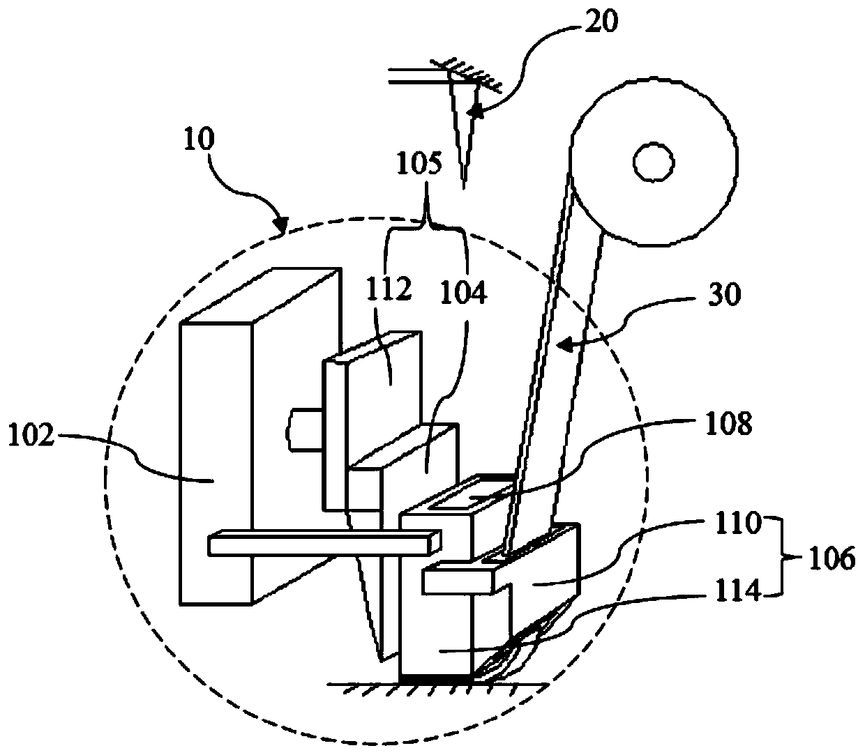
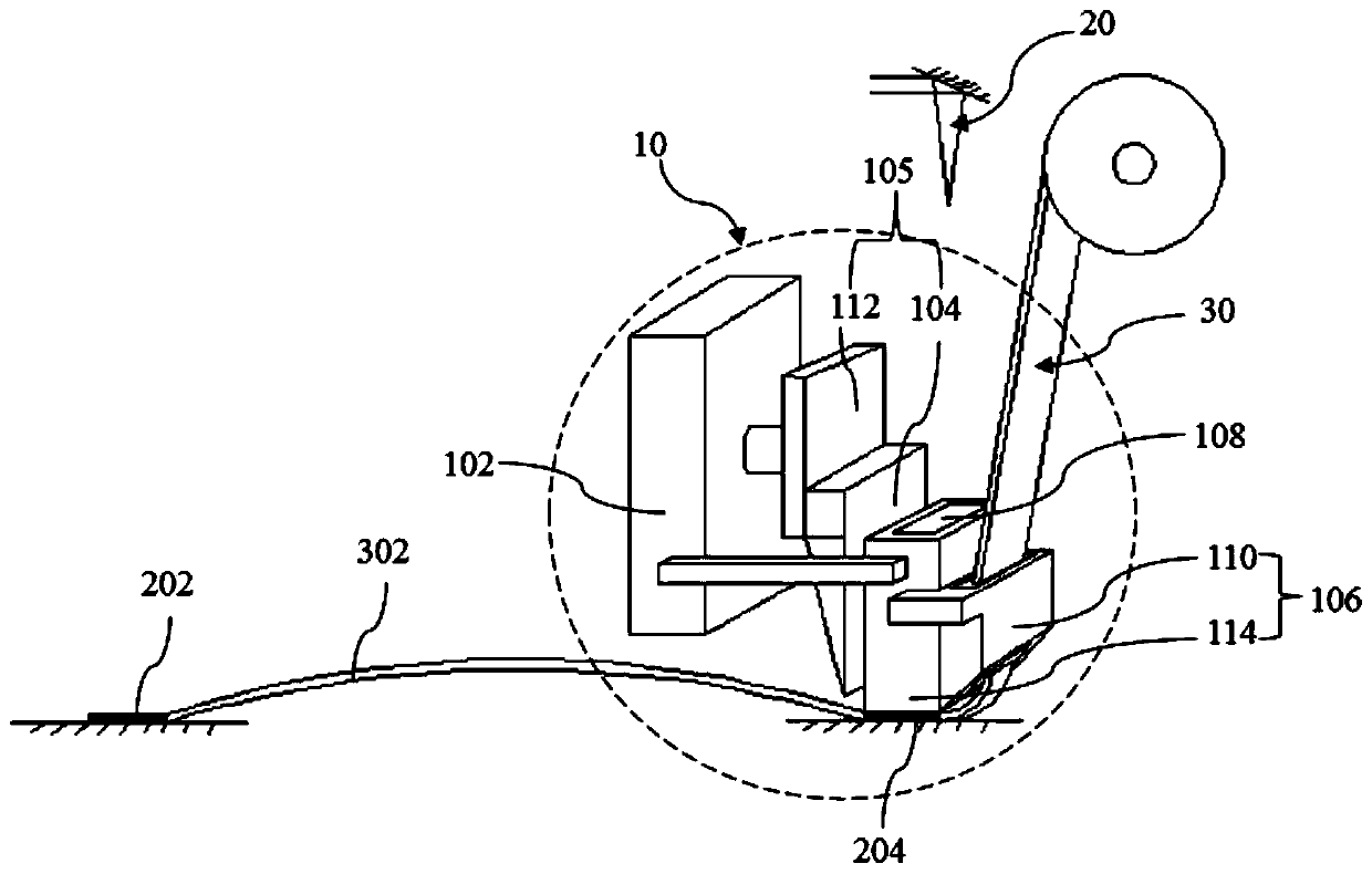
[0031] see Figure 1 to Figure 3 Shown, the laser welding device of the present invention comprises:

[0032] The welding assembly 10 includes a movable welding seat 102 and a pressing device 106 installed on the welding seat 102, and the pressing device 106 is provided with a through hole 108;

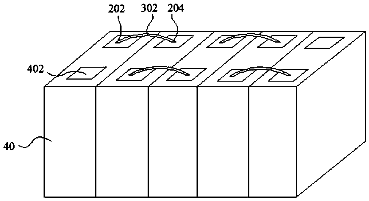
[0033] A connecting band 30, one end of the connecting band 30 is compressed on the pole 402 of the battery 40 through the pressing device 106; and

[0034] A laser generator 20, the laser emitted by the laser generator 20 ac...


PUM

PropertyMeasurementUnit
thicknessaaaaaaaaaa
thicknessaaaaaaaaaa
widthaaaaaaaaaa

Abstract

The invention discloses a laser welding device. The device includes a welding assembly, a connecting belt and a laser generator; the welding assembly includes a movable welding seat and a hold-down device installed on the welding seat, and the hold-down device is provided with through holes; one end of the connecting belt is tightly pressed on battery poles through the hold-down device; laser emitted by the laser generator acts on the connecting belt through the through holes; the hold-down device is also provided with a pressure sensor; and when the contact pressure between the connecting belt and the pole reaches a set value, the laser generator emits the laser and welds the connecting belt on the poles between batteries. Compared with the prior art, The beneficial effects of the deviceare as follows: 1) the device organically combines the high energy density of the laser and the high efficiency of welding, so that the welding of the connecting belt of the poles between the batteries can be realized, the weight of a battery module can be reduced, and welding efficiency can be enhanced; and 2) through the movable laser welding device, continuous welding can be realized, and falsewelding phenomenon can be reduced.

Description

technical field [0001] The invention belongs to the technical field of batteries, and more specifically, the invention relates to a laser welding device, which is used for welding the connecting strips of battery poles, and connecting the batteries in series or in parallel to form a battery pack. Background technique [0002] Lithium-ion batteries have the advantages of high energy density, high cycle times, and high efficiency, and have been widely used in various consumer electronics industries, electric vehicle industries, and energy storage device industries. However, the voltage and capacity of a single battery are small, which cannot meet the output of large capacity and high energy density. [0003] At present, in order to achieve large capacity and high energy density output, the existing technology uses laser welding to realize the connection between batteries. However, the laser welding method has the following problems: In order to increase the flow capacity, las...

Claims


Application Information

Patent Timeline
Patent Type & Authority Patents(China)
IPC IPC(8): B23P23/04B23D79/00
CPCB23D79/00B23K26/21B23P23/04
Inventor 陆巍巍陈宗火赵宾
Owner CONTEMPORARY AMPEREX TECH CO
Why Eureka
Try Eureka