Non-linear compensation method for miniature volumetric remote controlled hydrostatic actuator
A nonlinear compensation and remote control technology, applied in instruments, fluid pressure actuation devices, fluid pressure actuation system components, etc., can solve the problems of low efficiency, inability to meet the requirements of light weight, convenient assembly and disassembly, and complex structure at the same time
- Summary
- Abstract
- Description
- Claims
- Application Information
AI Technical Summary
Problems solved by technology
Method used
Image

Examples
Embodiment Construction
[0111] In order to facilitate the understanding of those skilled in the art, the present invention will be further described below in conjunction with the embodiments and accompanying drawings, and the contents mentioned in the embodiments are not intended to limit the present invention.
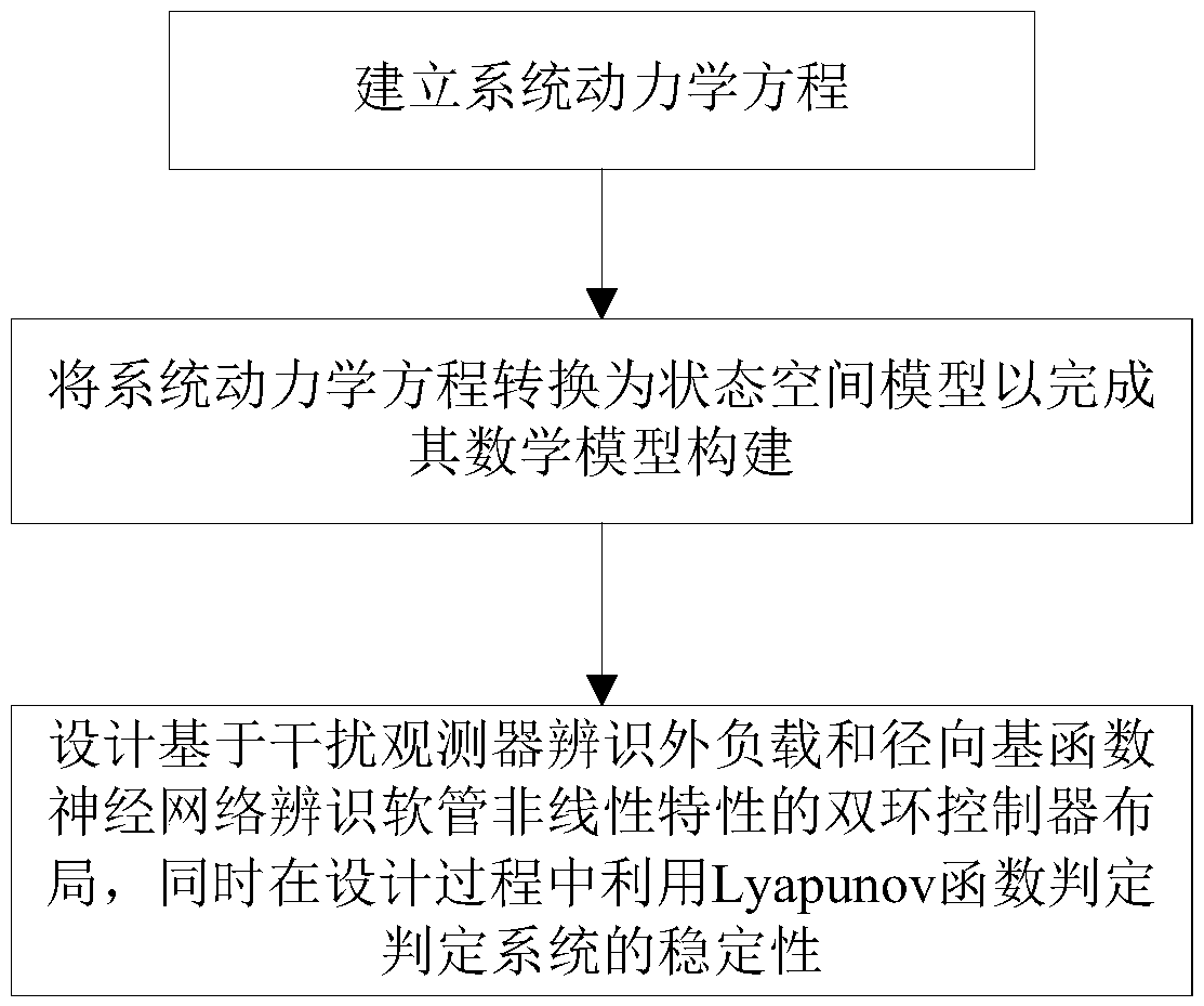
[0112] refer to figure 1 As shown, a non-linear compensation method for a miniature volumetric remote-controlled hydrostatic actuator of the present invention is based on a miniature double-cylinder volume control system. connection; including steps as follows:
[0113] Step 1: Establish the system dynamics equation;
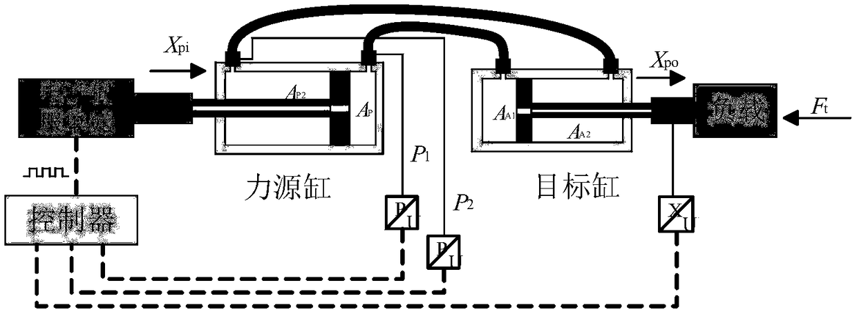
[0114] Such as figure 2 As shown in , the control cylinder is used as the control element driven by the servo unit and connected to the actuator cylinder through a slender hose, which is a dual-cylinder control strategy;
[0115] Assumptions: 1. Compared with the external load, the mass of the moving parts in the cylinder is negligible; 2. During the short driving process,...
PUM
 Abstract
Description
Claims
Application Information