
System for obtaining high-lumen-density green light source

A density and green light technology, applied in the field of lighting, can solve the problems of stray light, complex optical path, energy loss of optical path, etc., and achieve the effect of low energy loss, simple optical path and high lumen density

Active Publication Date: 2019-01-29
XUZHOU NORMAL UNIVERSITY
View PDF4 Cites 0 Cited by
  • Summary
  • Abstract
  • Description
  • Claims
  • Application Information

AI Technical Summary

Problems solved by technology

However, the optical path of this scheme is complicated, and in order to avoid the stray light problem caused by material scattering, optical components such as ground glass diffuser and dichroic mirror are used, which further increases the energy loss in the optical path; if this scheme is used to obtain high lumen density Green light source, need to further simplify the design of the optical path

Method used


Image

  • System for obtaining high-lumen-density green light source
  • System for obtaining high-lumen-density green light source

Examples


Embodiment 1

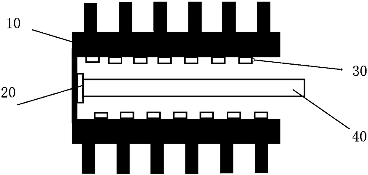
[0024] A system for obtaining high lumen density green light sources such as figure 1 As shown, it includes a heat sink 10, a laser diode module 30, and a fluorescent ceramic plate 40; wherein, the heat sink 10 is composed of two tungsten-copper heat sinks with symmetrical structures, and the inside of the heat sink 10 forms a cavity with only one side opening , a plurality of small holes with the same structure are evenly distributed on the upper and lower inner walls of the cavity; the laser diode module 30 is composed of 50 LD chips with a wavelength of 450.0nm and a peak power of 5.0W, and the LD chips are respectively fixed in the cavity of the heat sink 10 In the small holes on the upper and lower inner walls of each row, 25 chips are fixed in each row, and the upper and lower rows of chips are arranged alternately; the fluorescent ceramic plate 40 is horizontally fixed at the center of the cavity of the heat sink 10, and the two ends of the fluorescent ceramic plate 40 a...

Embodiment 2

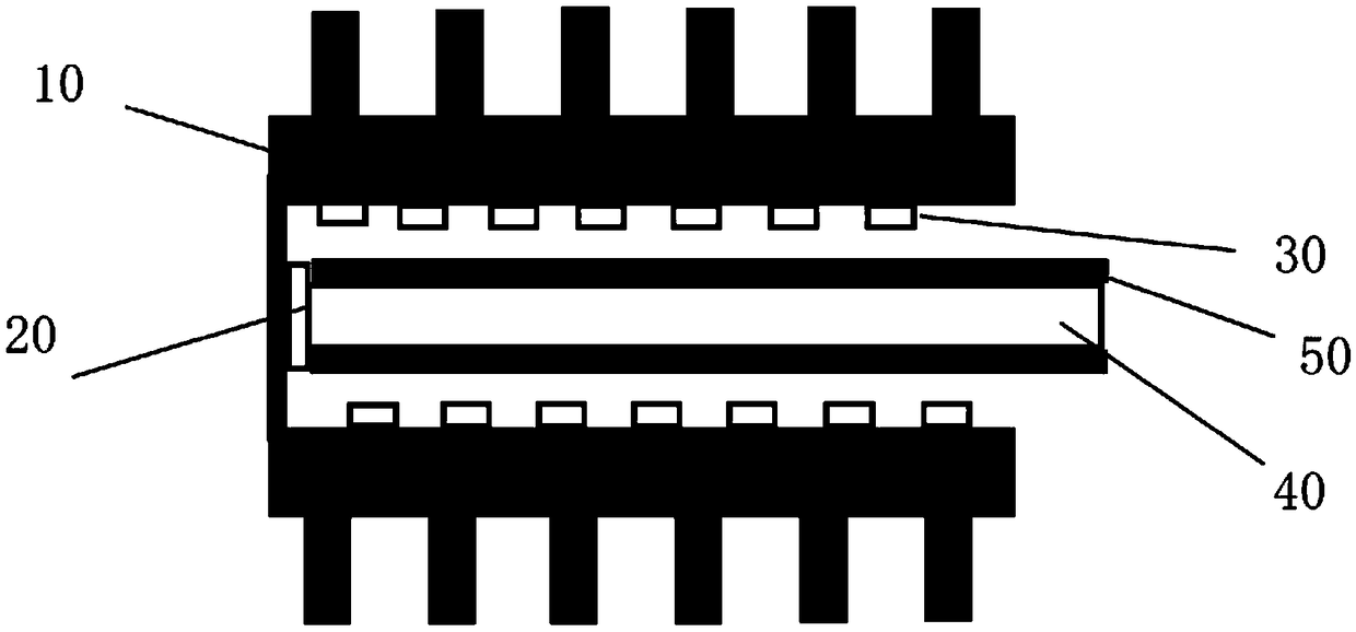
[0029] A system for obtaining high lumen density green light sources such as figure 2 As shown, it includes a heat sink 10, a laser diode module 30, and a fluorescent ceramic plate 40; wherein, the heat sink 10 is composed of two tungsten-copper heat sinks with symmetrical structures, and the inside of the heat sink 10 forms a cavity with only one side opening , a plurality of small holes with the same structure are evenly distributed on the upper and lower inner walls of the cavity; the laser diode module 30 is composed of 60 LD chips with a wavelength of 450.0nm and a peak power of 5.0W, and the LD chips are respectively fixed on the upper and lower inner walls of the heat sink 10 In the holes, 30 are fixed in each row, and the upper and lower rows of LD chips are arranged in a staggered manner; the fluorescent ceramic plate 40 is horizontally fixed at the center of the cavity of the heat sink 10, and the two ends of the fluorescent ceramic plate 40 are precisely polished an...


PUM

PropertyMeasurementUnit
thicknessaaaaaaaaaa
widthaaaaaaaaaa
lengthaaaaaaaaaa

Abstract

The invention discloses a system for obtaining a high-lumen-density green light source. The system comprises a heat dissipation base, a laser diode module and a fluorescent ceramic plate; the heat dissipation base is composed of and assembled with two tungsten-copper heat sinks which are symmetrical in structure, a cavity body with only one opening in one side is formed inside the heat dissipationbase, and a plurality of small holes with the same structure are uniformly distributed on the upper inner wall and the lower inner wall of the cavity body; the laser diode module is composed of a plurality of identical laser diode chips, the laser diode chips are all fixed in the small holes in the upper inner wall and the lower inner wall of the cavity body of the heat dissipation base, and theupper row of chips and the lower row of chips are arranged in a staggered mode; the fluorescent ceramic plate is horizontally fixed at the center position of the cavity body of the heat dissipation base, the two ends of the fluorescent ceramic plate are precisely polished, the end part of one end, extending into the cavity body of the heat dissipation base, of the fluorescent ceramic plate is plated with a film layer I, and the other end of the fluorescent ceramic plate is used as a light outlet; and the film layer I is an aluminum film. According to the system, a light path is designed according to the internal total reflection phenomenon of the fluorescent ceramic, simplicity and efficiency are achieved, and the high-lumen-density green light source with low optical expansion amount is obtained.

Description

technical field [0001] The invention relates to the field of lighting, in particular to a system for obtaining a green light source with high lumen density. Background technique [0002] Green light sources are widely used in projection, endoscopy, plant lighting and other fields. At present, the green light sources on the market generally use infrared lasers with a wavelength of 808nm to excite nonlinear crystals to generate 1064nm infrared light, and then generate 532nm green light after frequency doubling, which belongs to solid-state lasers and has low efficiency; It requires a higher indium composition; this induces a major physical change that changes the lattice constant and shortens the bandgap, and is not very efficient. With the continuous exploration of blue LED / LD by researchers, the WPE (wall-plug efficiency) has been improved by several orders of magnitude. Therefore, the green light source obtained by fluorescent conversion has higher efficiency. However, wi...

Claims


Application Information

Patent Timeline
Patent Type & Authority Applications(China)
IPC IPC(8): F21K9/232F21V7/22F21V9/08F21V19/00F21V29/70F21Y115/10
CPCF21K9/232F21V7/22F21V9/08F21V19/002F21V29/70F21Y2115/10
Inventor 陈浩甄方正康健孙景露舒欣宇李亚楠朱叶欣朱舒仪张乐
Owner XUZHOU NORMAL UNIVERSITY
Learn More