A software realization method of a DC charging pile monitoring system

A DC charging pile and monitoring system technology, applied in software design, instrumentation, data processing applications, etc., can solve problems such as software upgrades for developers, difficulty in maintenance work, real-time decline in complex logic control programs, and difficult expansion of communication function modules. , to meet the real-time requirements of the program, the program logic structure is clear, and the effect of meeting the real-time requirements

Active Publication Date: 2019-01-29
SHANDONG ELECTRICAL ENG & EQUIP GRP XINNENG TECH CO LTD
View PDF5 Cites 4 Cited by
  • Summary
  • Abstract
  • Description
  • Claims
  • Application Information

AI Technical Summary

Problems solved by technology

Some optimized traditional software adopts front/background program scheduling, and puts some urgent tasks into interrupts for processing. Although the real-time requirements of tasks are improved to a certain extent, the functional modules of these two methods It is relatively simple, and it is more suitable for tasks with low real-time requirements
When faced with the situation that there are many monitoring software function modules of the DC charging pile, the communication interaction is complicated, and the logic control is relatively complicated, the traditional software implementation method cannot meet the complex logic control, and when there are too many communication modules, the real-time performance of the program will decrease and the communication function modules will not be easy. E

Method used


Image

  • A software realization method of a DC charging pile monitoring system
  • A software realization method of a DC charging pile monitoring system
  • A software realization method of a DC charging pile monitoring system

Examples


Embodiment Construction

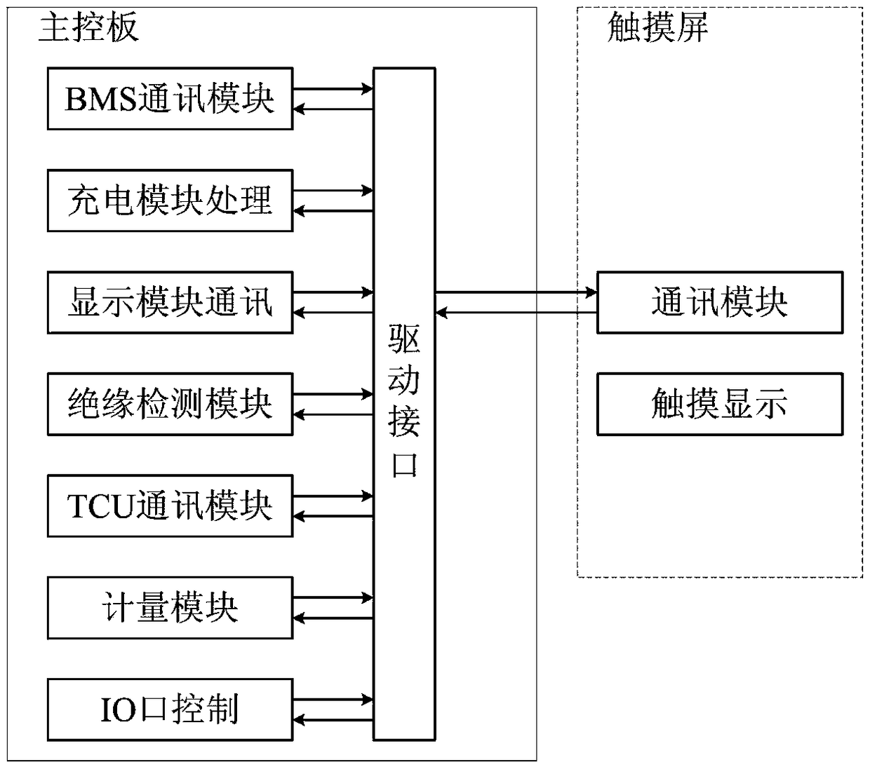
[0047] In order to make the technical solutions and advantages of the present invention clearer, the present invention will be further described in detail below in conjunction with the accompanying drawings. figure 1Shown is a schematic diagram of the functional architecture of the existing DC charging pile monitoring system. The DC charging pile monitoring system mainly includes CAN communication between the monitoring system and BMS, CAN communication between the monitoring system and the charging unit, CAN communication between the monitoring system and the charging module, 485 communication between the monitoring system and the insulation monitoring module, and communication between the monitoring system and the debugging touch screen. 485 communication, serial port communication between monitoring system and host computer software, monitoring system input and output IO control, monitoring system analog quantity acquisition module.

[0048] The CAN communication protocol b...


PUM


Abstract

The invention relates to a software implementation method of a DC charging pile monitoring system. A main state machine is arranged for that monitoring system of the DC char pile to be dispatched. Some of the complex large working states in the master state machine nest small state machines, each working state under each small state machine is added to timeout process, some common working states of each large working state are found out as the common migration invocation state under the main state machine. When each communication function module is involved in the master state machine scheduling process, the master state machine scheduling adopts information exchange mechanism, sets different information exchange flags, and adopts non-blocking transceiver processing mode to realize the bottom communication driving module. The invention can meet the real-time requirements of complex logic control and multi-task parallel operation, can meet the real-time requirements of the program whenthe communication module is too many, the communication function module is easy to expand, the program logic readability is strong, and the program logic is easy to upgrade and maintain.

Description

technical field [0001] The invention relates to the technical field of charging piles, and more specifically, to a software implementation method of a DC charging pile monitoring system. Background technique [0002] At present, the DC charging pile monitoring system software mainly includes CAN communication with BMS, CAN communication with billing unit, CAN communication with charging module, 485 communication with insulation monitoring module, 485 communication with debugging touch screen, and host computer software The serial communication, input and output IO control, analog acquisition and other modules have many functional modules, complicated communication interaction and complicated logic control. The traditional DC charging pile monitoring system software implementation method mainly adopts sequential scheduling, divides each functional module, and executes each functional module sequentially. Some optimized traditional software adopts front / background program sch...

Claims


Application Information

Patent Timeline
IPC IPC(8): G06F8/20G06Q10/06G06Q50/06
CPCG06F8/20G06Q10/0631G06Q50/06
Inventor 刘树通李圣单冠华莫文威薛铭
Owner SHANDONG ELECTRICAL ENG & EQUIP GRP XINNENG TECH CO LTD
Why Eureka
Try Eureka