Novel belt-shaped electron beam traveling-wave tube output structure

An output structure and electron beam technology, applied in the direction of the coupling device of the transit time type electron tube, etc., can solve the problems affecting the performance and life of the tube, the influence of the stability of the device performance, the limited working bandwidth, etc., to achieve good transmission performance and expand bandwidth. , the effect of compact structure

Inactive Publication Date: 2019-01-29
刘梅
View PDF0 Cites 0 Cited by
  • Summary
  • Abstract
  • Description
  • Claims
  • Application Information

AI Technical Summary

Problems solved by technology

However, since the size of the ridge waveguide is usually fixed, the electron beam will inevitably diverge during the transmission process and hit the waveguide wall, destroying the output structure and affecting the performance and life of the tube; and in order to increase the flow rate of electrons, The size of the ridge waveguide should not be too small, which will cause part of the electromagnetic wave to enter the collector region, which will affect the performance and stability of the device; at the same time, although the curved waveguide can guide the electromagnetic wave to separate from the electron beam, but because it is connected with If the ridge waveguide is connected, there will still be a certain number of electrons entering it with the electromagnetic wave due to the same partial velocity as the direction of the curved waveguide, thus bombarding the window, resulting in loss of the window; in addition, because the working bandwidth of the ridge waveguide connection structure is very limited , resulting in the working bandwidth of the whole pipe is also limited, generally only 30% of the relative bandwidth

Method used


Image

  • Novel belt-shaped electron beam traveling-wave tube output structure
  • Novel belt-shaped electron beam traveling-wave tube output structure
  • Novel belt-shaped electron beam traveling-wave tube output structure

Examples


Embodiment Construction

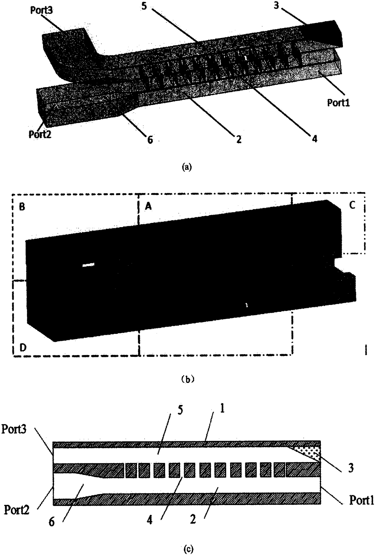
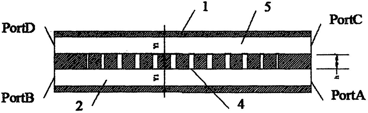
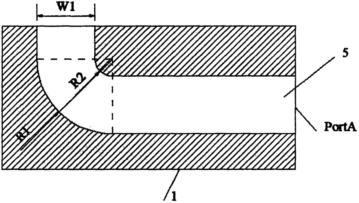
[0028] The present invention will be described in further detail below in conjunction with specific embodiments and accompanying drawings. For the convenience of description, only the output structure of the strip beam traveling wave tube of 36GHz-52GHz is used for detailed description, but the protection scope of the present invention is not limited thereto. Based on other frequency bands of the present invention, other strip beam traveling wave The tube output structure and any changes or replacements conceivable by anyone familiar with the technology within the technical scope disclosed in the present invention should be covered within the scope of the present invention. Therefore, the protection scope of the present invention should be determined by the protection scope of the claims.

[0029] Such as Figure 1-5 Shown is the output structure of the strip electron beam traveling wave tube in this embodiment, including a double rectangular waveguide coupling structure A, a...


PUM


Abstract

The invention provides a novel belt-shaped electron beam traveling-wave tube output structure. The output structure comprises a double rectangular waveguide coupling structure, an arc-shaped waveguidebend, a monoclinic split medium matched load and a linear gradual-changing section, wherein the double rectangular waveguide coupling structure comprises an upper waveguide and a lower waveguide, theupper waveguide is an electromagnetic wave channel, and two ends of the electromagnetic wave channel are an electromagnetic wave output port and a matched load port respectively; the lower waveguideis an electron beam channel, two ends of the electron beam channel are an electron beam output port and an electron beam input port respectively; the a rectangular coupling seam is arranged between the wave channel and the electron beam channel, the arc-shaped waveguide bend is connected to the electromagnetic wave output port, the monoclinic split medium matched load is arranged at the matched load port, and the linear gradual-changing section is connected to the electron beam output port. The novel structure can effectively achieve beam and wave separation, provide a wide electron beam channel, an isolation high-frequency interaction region and a collector region and have a good transmission coefficient on a wide frequency band.

Description

technical field [0001] The invention belongs to the field of microwave vacuum devices, and relates to an output structure for high-power microwave vacuum devices, in particular to an ultra-wideband output structure of a strip-shaped electron beam traveling wave tube. Background technique [0002] The ribbon beam microwave vacuum device is a device that converts the kinetic energy of electrons carried by the ribbon beam into microwave energy through the movement of electrons in vacuum. The electron gun produces a beam of electrons in the ribbon beam, and the electron beam moves towards the high-frequency structure under the constraint of the voltage between the anode and the cathode and the applied magnetic field. The electron beam interacts with the high-frequency field in the high-frequency structure, converting the energy of the electrons into high-frequency energy. In order to realize the beam interaction process, it is necessary to couple the high-frequency input signal...

Claims


Application Information

Patent Timeline
Patent Type & Authority Applications(China)
IPC IPC(8): H01J23/38
CPCH01J23/38
Inventor 刘梅
Owner 刘梅
Why Eureka
Try Eureka